We’ve said it before and we’ll say it again: being able to build your own radios is the best thing about being an amateur radio operator. Especially low-power transmitters; there’s just something about having the know-how to put something on the air that’ll reach across the planet on a power budget measured in milliwatts.
This standalone WSPR beacon is a perfect example. If you haven’t been following along, WSPR stands for “weak-signal propagation reporter,” and it’s a digital mode geared for exploring propagation that uses special DSP algorithms to decode signals that are far, far down into the weeds; signal-to-noise ratios of -28 dBm are possible with WSPR.
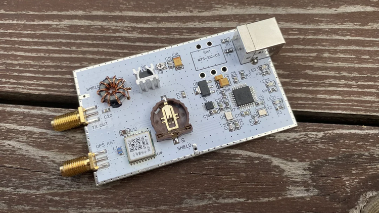
Because of the digital nature of WSPR encoding and the low-power nature of the mode, [IgrikXD] chose to build a standalone WSPR beacon around an ATMega328. The indispensable Si5351 programmable clock generator forms the RF oscillator, the output of which is amplified by a single JFET transistor. Because timing is everything in the WSPR protocol, the beacon also sports a GPS receiver, ensuring that signals are sent only and exactly on the even-numbered minutes. This is a nice touch and one that our similar but simpler WSPR beacon lacked.
This beacon had us beat on performance, too. [IgrikXD] managed to hit Texas and Colorado from the edge of the North Sea on several bands, which isn’t too shabby at all with a fraction of a watt.
Thanks to [STR-Alorman] for the tip.
[via r/amateurradio]


What am I missing, there doesn’t seem to be any filtering on the output to suppress harmonics which is decidedly antisocial, especially as the BS170 PA can make reasonable power into low VHF?
You are absolutely correct. There is no filtering. The output connector is marked ‘Antenna’. I suspect there will be more than one of these interference generators directly connected to an antenna and then forgotten. This and others like it should not be published without strong warnings that they probably do not meet spurious suppression standards.
Eh. The law limits harmonic emissions in terms of the ratio to primary frequency. Thats a good law when applied to Bubba’s 1500 watt amp, but even the total power output here is still way less than the harmonics of a “legal” full power transmitter. Spirit of the law versus letter of the law I guess…
We suffer enough interference from all sorts of domestic and industrial garbage out there, it really doesn’t seem sensible to add to it if wecan avoid it.
It’s really not difficult to build and stick a LPF in there so why not be a good neighbour and ‘do your bit’ to help keep the bands a little bit more useable?
Plus, Si5351 harmonics can be less than 17dB down on fundamental, run that through a hacky little amp that gets it to 27dBm (half a watt) and suddenly you could have 10dBm worth of interference if there’s no LPF.
Meanwhile, Bubba’s running full power on his well set up and filtered 1500W amp
The harmonic is 60dB (or better) down on fundamental at 2dBm.
Your ‘Eh.’ little WSPR box is causing more interference.
The FCC limit for 1500W is much higher attenuation than the required attenuation for low power.
The exact rules are:
c.) All spurious emissions from a station transmitter must be reduced to the greatest extent practicable. If any spurious emission, including chassis or power line radiation, causes harmful interference to the reception of another radio station, the licensee of the interfering amateur station is required to take steps to eliminate the interference, in accordance with good engineering practice.
(d) For transmitters installed after January 1, 2003, the mean power of any spurious emission from a station transmitter or external RF power amplifier transmitting on a frequency below 30 MHz must be at least 43 dB below the mean power of the fundamental emission. For transmitters installed on or before January 1, 2003, the mean power of any spurious emission from a station transmitter or external RF power amplifier transmitting on a frequency below 30 MHz must not exceed 50 mW and must be at least 40 dB below the mean power of the fundamental emission. For a transmitter of mean power less than 5 W installed on or before January 1, 2003, the attenuation must be at least 30 dB. A transmitter built before April 15, 1977, or first marketed before January 1, 1978, is exempt from this requirement.
So we see, the law is for this transmitter is that harmonics must be at least 30 dB below the fundamental.
+1
Though to be fair, it’s the duty of the radio amateur to make sure his/her equipment doesn’t cause interference, the maker of kits can’t be held responsible here.
Also, it’s still possible to install a filter device in line.
This is usually being done by amateurs and CBers who have a linear amp.
The filter is usually a low pass filter and attached prior antenna.
Though it doesn’t hurt to install a second one before the libear, so the linear won’t amplify any harmonics to begin with.
I think it would be an easier sell to have the filters onboard rather than taking the chinese path of design.
Good day! In the operating instruction of the device there is information about radiated harmonics and the necessity to use bandpass filters. Filters are deliberately not added to the PCB, because it is much easier to connect one external filter for a specific band than to place them inside the device. In addition, different people may require different transmission ranges and would need to design a separate filter for each, which would require to much PCB space.
Good day! The operating instruction (GitHub located) for the device includes information about emitted harmonics and the necessity of using band-pass filters. The filters were intentionally not added to the printed circuit board because it is much easier to connect an external filter for a specific band than to place them inside the device. Moreover, different people may require different transmission bands, and for each of them, a separate filter would need to be designed, which would require a lot of space on the printed circuit board. If such filters were integrated into the device, it would no longer be as compact.
Out of curiosity, does it really matter if the power levels are so low?
Yes
Won’t beat Meshtastic
In terms of miles per watt, yeah, it wipes the floor with Meshtastic and accomplishes that with considerably less complexity.
However, you’re comparing chalk and cheese, Meshtastic and WSPR are two completely different technologies with completely different aims and purposes.
Shh, shh, shh! She’s a scientist!
Do you have any studies or data backing this up? It would be quite the feather in it’s cap if Meshtastic was able to do this with its short bit of text.
dBm is a measure of power. SNR is expressed in terms of dB. A SNR of -28 dB is equivalent to trying to understand someone speaking 100 feet away while someone else is speaking at the same volume 4 feet away.
This is crucial. -28 dBm wouldn’t be very good, the average smartphone can still make calls at -100 dBm.
I always find the “down to -28 db SNR” confusing as hell because it suggests the signal is weaker than the noise floor, which isn’t possible.
In reality this is the result of a strange way to look at the signal: WSPR (like FT4, FT8, JT65, JT9) use a 2500 Hz wide band, but the actual transmission uses subcarriers that are just a few Hz wide and put all the sender’s energy into that. To come to the “-28 dB SNR” statement, you have to compare the sum of all noise received in the full 2500 Hz band to the signal. Which is obviously misleading, the detector never looks at the rest of the band, it already knows it only has to look at very specific parts of it. So it isn’t affected by that other noise.
The true energy per symbol to noise power spectral density ratio of WSPR if the receiver sees -28 db on the full 2500 Hz band at its end is -28 + (10 * log(2500/1,475)) = 4,2915 db. In wireless communications, 12 dB are often considered to be the lower bound for a functional transmission. WSPR still works at about a sixth of that limit. But 4,2915 dB still means the receiver sees a signal that’s about three times stronger than the noise floor.
This. A peeve of mine too.
A case for an exception might be made when spectral spreading is used, like in GPS or LoRa modulation, or CDMA in general.
Well, thanks for that explanation.
So, in order for the signal to be received, the receiver needs to know the carrier frequency, the sidebands, the time of transmission, and possibly its location (to aim the receiving antenna).
That information would likely be made Known through another, more reliable means of communication?
TX and RX need synchronised time, NTP or GPS are good enough.
Carrier frequency is determined by band plans (for Ham use anyway)
“Sidebands” are set by signaling protocol.
Signals can be lower than the noise floor and still be decodable. For example with 1MHz BW and -30dB SNR the maximum capacity is around 1.5kbps. Of course the receiver process will ‘shape the noise’ so an internal apparent positive SNR is obtained.
In practice this is normally done with a high performance FEC.
SNR is simply a limited measure and is almost useless for comparing. What you usually want in the en it’s the dreaded Eb/N0 (energy per bit over Noise density) performance :)
https://www.eletrica.ufpr.br/evelio/TE111/Eb_N0.pdf <- that pdf is pure gold on the topic in my opinion.
chalk&cheese=tears,fanks.
Great looking board and project! For the invested effort, consider a wee bit more by adding a useful payload as well, like some telemetry. Here is a link to this sort of concept: http://www.va3rom.com/docs/RM057.pdf
we need packet radio , bbs bring back and interface to quancheng, baofeng or other cheap radios