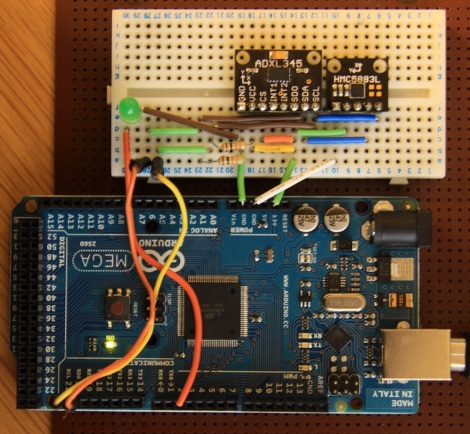
If you’re familiar with using a compass (the tool that points to magnetic north, not the one that makes circles) the concept of holding the device level makes sense. It must be level for the needle to balance and rotate freely. You just use your eyes to make sure you’re holding the thing right. Now think of a digital compass. They work by measuring the pull of a magnetic field, and have no visual method of showing whether they’re level or not. To ensure accurate readings you might use an accelerometer to compensate for a tilted magnetometer.
The process involves taking measurements from both an accelerometer and a magnetometer, then performing calculations with that data to get a true reading. Luckily the equations have been figured out for us and we don’t need to get too deep into trigonometry. You will, however, need to use sine, cosine, and arctangent in your calculations. These should be available in your programming language of choice. Arduino (used here) makes use of the avr-libc math library to perform the calculations.


