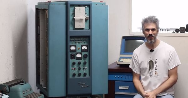
When it’s the 1950s and you are tasked to design a computer system that features not only CPU registers but also a certain amount of RAM, you do not have a lot of options. At this point in time, discrete logic was the rule, and magnetic core memory still fairly new and rather expensive. This is where the rotating drum comes in, which is somewhat like a cross between an old-style cylinder record and a hard drive. In a recent [Usagi Electric] video, a 1950s Bendix G15 system is demonstrated, which features such a rotating drum device, alongside both tube-based circuits and newfangled diode-based circuitry.
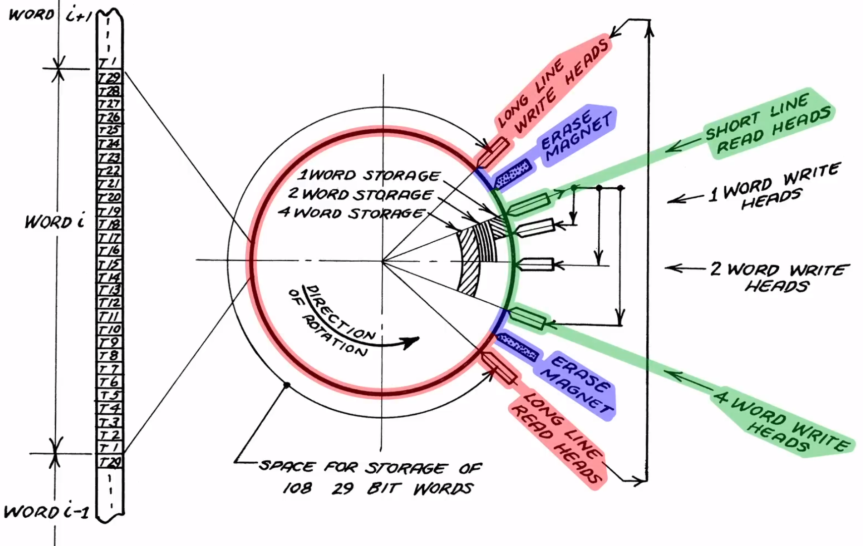
This particular unit was borrowed from the System Source museum, with the intent to restore it to a working condition. Part of this process involved figuring out the circuitry, which was made easy by the circuit schematic drawings that came with the original machine. According to the official brochure by the manufacturer, the ‘short lines’ that are intended for the CPU registers, the access time was less than 1 millisecond, which is pretty darn fast considering the era and the discrete CPU’s clock speed.
For the drum itself, however, popping the cover off the unit showed that it had suffered some damage that had resulted in the multiple heads contacting the surface. Despite this disappointment, it’s not the end of the restoration, however. The museum has one more Bendix G15 standing around, with a rotating drum unit that looks to be in mint condition. The damaged magnetic coating on the other rotating drum may conceivably be resurfaced, which if successful could provide new hope to a lot of retro systems out there that also use magnetic media, whether in drum or disk format.
Continue reading “Random Access Memory From A Rotating Drum In A Bendix G15”