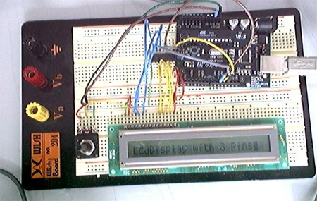
Normally driving an LCD requires seven connections to pins on the display, but by using a shift register, [Phillip Warner] at Arduino Playground was able to drive an LCD using only 3 wires. The method is cheaper than a serial LCD, but you’ll mainly save yourself a lot of effort and time by using it.
[Warner] used a HEF4094 chip to group the lines together and a variable resistor to control the contrast. A zip file with the requisite code to make this work can be found in the post.
[via YourITronics]


Actually this is better than using a serial LCD backpack since it has a synchronous clock. You can bit bang this as slowly and irregularly as you’d like, and don’t need to waste a UART.
better: http://ouwehand.net/~peter/lcd/lcd_examp.shtml
Quote “Replace the HEF4094D with a plain 8-bit shift register like the 74HC164 (it will be slightly cheaper). It has no STR input, so the PIC’s RB3 just connects to the LCD module’s EN signal.” This method was used in the AVR DDS Signal Generator project as well.
This has been done time and time again, i figured it would have been here long ago. A thing to consider about this approach is the additional cost in terms of board space. Most of the time it is more effective to simply move to a greater pin mcu. The cost generally works out to be the same and you end up saving some space.
hmm, actually i’ve done it with two wires :)
74HC164, a diode and a resistor. wire the LCD’s D4-D7 to HC164 Q4-Q7, RS to Q3 and R/!W to ground. wire a diode between HC164 Q0 and the LCD’s E line, cathode to Q7. now finish off by adding a 10k resistor between DATA_IN and the LCD’s E line.
the idea isn’t mine, Myke Predko came up with it – the details are somewhere on rentron.com. i took one look at his code and rewrote it to suit my style :)
PIC code here: http://www.piclist.com/techref/io/lcd/unilcd.htm
works for 4-bit and 2-wire serial HD44780 LCDs
actually, a few points about the article…
1) why bother wiring R/W to the shiftreg if you can’t actually read back through it? seems like a silly plan. keeping track of what’s on a 16×2 LCD in a micro isn’t exactly hard anyway, but i can’t think of a situation where i’ve ever needed to read back from a HD44780 panel. now a graphics LCD, that’s a different story.
2) hef4094 might not be the best choice.. ime the 74HC164 and similar are somewhat cheaper, and use less power. nice idea though.
3) ugh, you have to send the control byte three times? if you’re going to do 3-wire control, use an unlatched S/R and wire the LCD’s E line straight to the circuit. saves clock cycles – load the control byte then toggle E :)
i’m not intending to rubbish the idea… just commenting on how you could do it better.
i really should write up that tutorial on reverse engineering pinouts for controllerless graphics lcds with nothing more than a multimeter… and maybe document some of my PIC tricks too. argh, need more spare time!