Mapping The Nintendo Switch PCB

As electronics have advanced, they’ve not only gotten more powerful but smaller as well. This size is great for portability and speed but can make things like repair more inaccessible to those of us with only a simple soldering iron. Even simply figuring out what modern PCBs do is beyond most of our abilities due to the shrinking sizes. Thankfully, however, [μSoldering] has spent their career around state-of-the-art soldering equipment working on intricate PCBs with tiny surface-mount components and was just the person to document a complete netlist of the Nintendo Switch through meticulous testing, a special camera, and the use of a lot of very small wires.

The first part of reverse-engineering the Switch is to generate images of the PCBs. These images are taken at an astonishing 6,000 PPI and as a result are incredibly large files. But with that level of detail the process starts to come together. A special piece of software is used from there that allows point-and-click on the images to start to piece the puzzle together, and with an idea of where everything goes the build moves into the physical world.

[μSoldering] removes all of the parts on the PCBs with hot air and then meticulously wires them back up using a custom PCB that allows each connection to be wired up and checked one-by-one. With everything working the way it is meant to, a completed netlist documenting every single connection on the Switch hardware can finally be assembled.

The final documentation includes over two thousand photos and almost as many individual wires with over 30,000 solder joints. It’s an impressive body of work that [μSoldering] hopes will help others working with this hardware while at the same time keeping their specialized skills up-to-date. We also have fairly extensive documentation about some of the Switch’s on-board chips as well, further expanding our body of knowledge on how these gaming consoles work and how they’re put together.

NASA Blames Probe Chute Failure On Wire Labels

When NASA’s OSIRIS-REx sample return capsule screamed its way through the upper atmosphere, it marked the first time the space agency had brought material from an asteroid back to Earth. Hundreds of thousands tuned into the September 24th live stream so they could watch the capsule land at the Utah Test and Training Range. But about ten minutes before the capsule was set to touchdown, keen eyed viewers may have noticed something a bit odd — when ground control called out that the vehicle’s drogue parachute was commanded to deploy…nothing seemed to happen.

Now NASA knows why it didn’t work as expected, and it ended up being the sort of Earthly problem that we’d wager a few in this audience have run into themselves from time to time.

Continue reading “NASA Blames Probe Chute Failure On Wire Labels”

DIY LED Bulb Lacks Correct Lugs, So M3 Bolts To The Rescue

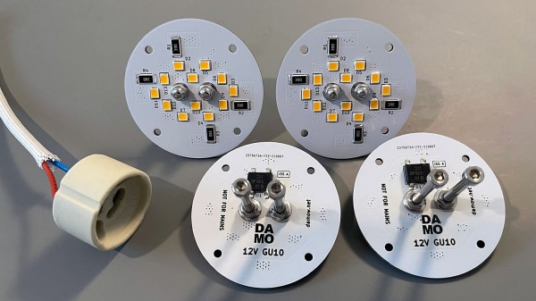
[Damo] has an interesting LED bulb project with a neat twist: he converted some outdoor lighting to 12 V LED lighting with some self-designed bulb replacements and decided to reuse the existing GU10 sockets and wiring. That meant putting GU10 lugs onto his custom PCBs, but he ran into a snag.

These GU10 bulb lugs are tough to buy in small quantities. Luckily, M3 socket head bolts are a near-perfect match.

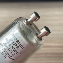
Those distinctive lugs that twist into GU10 sockets? [Damo] simply couldn’t find anywhere offering to sell them in small quantities. So he did what any enterprising hacker would do and found a substitute that was both accessible and economical: M3 bolts. Apparently, socket-headed M3 bolts are pretty much identical in size to GU10 lugs. Who’d have thought?

[Damo]’s retrofit worked great, and thanks to M3 bolts he was able to re-use the existing weatherproof wiring and sockets in his yard. His design files are here on GitHub.

We do love using things for other than their intended purpose, but as [Damo] points out, GU10 sockets are normally connected to mains power. So if you decide to use his design (or use GU10 sockets for your own purposes), be aware that you’ll have hardware that looks interchangeable with other (mains-connected) sockets, but isn’t. Be mindful of that, and take appropriate precautions. Avoiding electrical oopsies is always worth putting effort into, after all.

Measuring current draw of home shop tools

Using Homebrew Coils To Measure Mains Current, And Taking The Circuit Breaker Challenge

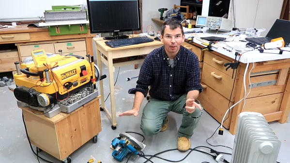
Like many hackers, [Matthias Wandel] has a penchant for measuring the world around him, and quantifying the goings-on in his home is a bit of a hobby. And so when it came time to sense the current flowing in the wires of his house, he did what any of us would do: he built his own current sensing system.

What’s that you say? Any sane hacker would buy something like a Kill-a-Watt meter, or even perhaps use commercially available current transformers? Perhaps, but then one wouldn’t exactly be hacking, would one? [Matthias] opted to roll his own sensors for quite practical reasons: commercial meters don’t quite have the response time to catch the start-up spikes he was interested in seeing, and clamp-on current transformers require splitting the jacket on the nonmetallic cabling used in most residential wiring — doing so tends to run afoul of building codes. So his sensors were simply coils of wire shaped to fit the outside of the NM cable, with a bit of filtering to provide a cleaner signal in the high-noise environment of a lot of switch-mode power supplies.

Fed through an ADC board into a Raspberry Pi, [Matthias]’ sensor system did a surprisingly good job of catching the start-up surge of some tools around the shop. That led to the entertaining “Circuit Breaker Challenge” part of the video below, wherein we learn just what it really takes to pop the breaker on a 15-Amp branch circuit. Spoiler alert: it’s a lot.

Speaking of staying safe with mains current, we’ve covered a little bit about how circuit protection works before. If you need a deeper dive into circuit breakers, we’ve got that too.

Continue reading “Using Homebrew Coils To Measure Mains Current, And Taking The Circuit Breaker Challenge”

Print-in-Place Connectors Aim To Make Wiring Easier

One thing some of us here in the United States have always been jealous of is the WAGO connectors that seem so common in electrical wiring everywhere else in the world. We often wonder why the electrical trades here haven’t adopted them more widely — after all, they’re faster to use than traditional wire nuts, and time is money on the job site.

Wago 221 compact lever connector via the Wago YouTube channel

This print-in-place electrical connector is inspired by the WAGO connectors, specifically their Lever Nut series. We’ll be clear right up front that [Tomáš “Harvie” Mudruňka’s] connector is more of an homage to the commercially available units, and should not be used for critical applications. Plus, as a 3D-printed part, it would be hard to compete with something optimized to be manufactured in the millions. But the idea is pretty slick. The print-in-place part has a vaguely heart-shaped cage with a lever arm trapped inside it.

After printing and freeing the lever arm, a small piece of 1.3-mm (16 AWG) solid copper wire is inserted into a groove. The wire acts as a busbar against which the lever arm squeezes conductors. The lever cams into a groove on the opposite wall of the cage, making a strong physical and electrical connection. The video below shows the connectors being built and tested.

We love the combination of print-in-place, compliant mechanisms, and composite construction on display here. It reminds us a bit of these printable SMD tape tamers, or this print-in-place engine benchmark.

Continue reading “Print-in-Place Connectors Aim To Make Wiring Easier”

An Open Source Tool To Document Your Wiring

Most of us are familiar with the tools available to create circuit diagrams, as generally that’s the first step towards producing a custom PCB. But that about the cables and wiring harnesses that don’t live on your board? How do you easily document the rat’s nest perfectly logical wiring of your latest and greatest creation?

That’s precisely the question that led [Daniel Rojas] to create WireViz. This open source Python tool takes human readable input files and turns them into attractive and functional visualizations of where all the wires in your project are going. It can even be used to generate a Bill of Materials that documents the lengths of wire required and types of connectors needed to hook everything up.

If you’re still using pre-made cables to connect all of your components together, than you might not immediately see the benefit of a tool like this. But as we’ve talked about in the past, the creation of custom wiring harnesses is something that serious hardware hackers should become familiar with. Yes it takes more effort, but the end result is worth it. With a tool like WireViz, the creation of a bespoke harness for your next project just got a little bit easier.

[Daniel] has done a fantastic job documenting this project, providing not only a tutorial on how to feed and care for your WireViz, but a gallery of examples that shows off the kind of complex wiring the tool can help make sense of. But there’s plenty more to be done, and he’s happy to get feedback or code contributions from anyone who wants to get involved.

Strike A Solder Joint Behind Enemy Lines

Imagine you’re out behind enemy lines in WW2, setting up demolition charges that may save the lives of your fellow soldiers. How do we make a solid connection between wires that will last? One of the solutions that were used by the OSS and SOE, the predecessors to the CIA and British Secret Service, were self soldering sleeves that could be lit like a match. [ElementalMaker] managed to get his hands on a box of these sleeves, and found that they work incredibly well, even after more than half a century.

The sleeves consist of a copper tube with solder and flux inside, and wax-covered pyrotechnic compound around the outside. A small blob of striker compound similar to a match head is used to set the soldering process in motion, using the striker surface on the outside of the oversize matchbox that the sleeves are packed in. The pack that the [ElementalMaker] got was made in 1964, but is supposedly no different from those used in WW2.

When lit, the pyrotechnic compound does not create any flame, it only smolders, probably to make it safer to use, and avoid detection at night. As the solder inside the sleeve melts, the operator is supposed to push the wires further into the tube to make them overlap. Although [ElementalMaker] didn’t cut open the sleeves, it definitely looks like a good joint, with solder oozing from the ends. Check out the video after the break! If you want to get your hands on a pack of these sleeves, it looks like a military surplus store in the UK managed to source some.

As horrible as war is, it’s undeniable that it inspires some creative innovations. Like soldiers hacking together parts from multiple guns to serve their immediate needs, or making guns shoot through spinning propellers without damaging them. Continue reading “Strike A Solder Joint Behind Enemy Lines”