A logic analyzer records bus communications between two chips. If you’ve ever had a problem getting two chips to talk, or wanted to reverse engineer a protocol, a logic analyzer is the tool you need to spy on the bus.
The Logic is a USB logic analyzer with eight channels and sampling rates up to 24MHz. Among hobby-level logic analyzers, the Logic has a good mix of features and decent sampling rates. We’ve been following Joe Garrison’s work on the Logic for a long time. If you’ve ever considered bringing a product to market, you can learn a lot from Joe’s blog that documents his development process.
When it debuted, the Logic was so popular that it was hard to buy one. It’s now widely available, and Saleae gave us one to try. Read our review below.
Logic Analyzers vs. Oscilloscopes
Most modern electronics projects will benefit more from a logic analyzer than an oscilloscope. An oscilloscope displays a graph of an analog voltage as it varies over time, such as the curve of a sine wave. A logic analyzer only detects high and low digital states, but it records many signals simultaneously. Logic analyzers dump data to a computer for analysis, very few oscilloscopes have this feature.
What you get

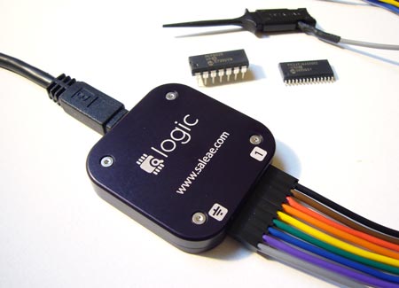
The Logic comes packaged in an external hard drive case. The analyzer is a small, anodized aluminum puck with laser etched signal markers. It’s much smaller than we expected, slightly smaller than a compact flash storage card. A mini-B USB cable is included.
A heavy-gauge cable and nine E-Z-Hooks (5 shown) connect the Logic to a circuit. The hooks are a really nice touch; press the back of the hook to expose a pair of tweezers, grab onto a signal wire, and retract to hold it in place. The retractable tweezers prevent accidental shorts on cramped test circuits.
Software isn’t included, instead you get instructions to download the latest version from the Saleae web site. We always download the latest software, so we appreciate that there’s one less CD headed to the landfill.
Right now, only Windows XP/Vista software is available, but Mac and Linux software should be ready soon. Warning: the Windows version requires .NET 3.5, download the redistributable off-line installer if you don’t want to give internet access to Microsoft’s online installer.
Using it

Using the Logic is simple. Connect the gray ground wire to the ground of the test circuit, then hook into the signal lines you want to record. We connected it to the 32K SPI SRAM that we demonstrated earlier this week. SPI has four important signals; enable, data in, data out, and clock. The E-Z-Hooks make it dead simple to tap into the signals without accidental shorts.
Be mindful of wire orientation. We associate a black wire with ground, but the Logic cable uses gray. Comments on SparkFun’s product page suggest that reversing the connections will damage the Logic.

The software analyzes and displays signal captures. The primary configuration options are the sampling rate (200KHz-24MHz) and number of samples (millions to billions). We were able to sample at 24MHz, but the top speed depends on how much other stuff is using the USB bus. A 24MHz sampling rate can capture signals up to 12MHz, we found this suitable for all the protocols we use. The total number of samples is limited only by the available PC RAM.
There’s a four level trigger that watches the signals, and waits for a specific combination before it starts recording samples. Since we’re analyzing SPI, the most logical place to start capturing is when the SPI enable signal drops at the beginning of a bus transaction. We set the Logic trigger to start sampling when SPI enable is 0 by changing its trigger to ‘0’.

We really like the profiles that decode most common serial protocols; 1-Wire, I2C, SPI, and asynchronous serial. CAN and other protocols will be added eventually.
Profiles suggest names for each signal, and convert squiggly lines into readable byte values. This is a really awesome feature. Without it, you’d have to count clock pulses to identify byte boundaries, and then manually decode the values.
This transaction shows the host issue the read configuration register command (0x05), and the SRAM response (0x41).
![]()
We also tried the 1-Wire decoder with a DS2431 EEPROM. The software identified the 1-Wire reset command, and the 1-Wire ‘search rom’ command (0xf0).
A look inside

The Logic is based on the Cypress Semiconductor CY7C68013A-56PVXC, an Intel 8052 microcontroller with a USB peripheral. The 8052 is an enhanced version of the well-known 8051. We can also identify a 24MHz crystal, which is probably multiplied to 48 or 96MHz by an internal phase-locked loop.
Conclusion
Logic analyzers take the guess work out of debugging inter-chip communication. If you can’t see what’s going on, the best you can do is guess about the problem. When a project won’t work, 99% of the time we can solve the problem immediately by looking at the signals with a logic analyzer. Without it, there’s no easy way to know what’s happening.
The Logic records 8 channels at 24MHz. The Windows software has useful features, and there’s an SDK if you want to write your own apps. Linux and Mac versions are under development. We really like this logic analyzer, and plan to use it to illustrate future articles.
The Logic is $149 at the Saleae website and SparkFun, and Joe is working on EU distribution. If you’re interested in the Logic, but aren’t ready to buy, you can download the software and try it in demo mode.
Hack a Day review disclosure: We asked for a Logic and Saleae sent it to us


@NKC Electronics: It seems pretty obvious from your statement – “It is a real logic analyzer, not a toy like the saleae device.” – that your use of the word “toy” is derogatory – not “fun”. Now you are back-pedaling to save face.
It is also fairly obvious that you have hijacked this forum thread in hopes of selling products on your website. I guess you also see that as “fun”. Some (including me) see it as dishonorable. Go advertise on google.
Thanks for linking to the LAP-16032U.
This is a really interesting tool. I’d bet that it’s similar to our CPLD development board: a 32K SRAM (128K or 1Mbit in the newer versions) with a CPLD-based trigger (1 level) and counter. I suppose it could also be entirely implemented in a FPGA, but the speed (75MHZ) seems about right for a CPLD.
The parallel SRAM and counter approach is great for high-speed, short captures. The Saleae Logic and other Cypress-based LAs are great if you need to capture extended sequences at reasonable speeds.
We use a LA primarily for debugging our own devices, so it’s usually no problem to slow the clock/interface to a speed that works within the limits of the logic analyzer.
@visitor, at least I show my face… I don’t think it is dishonorable to spread information and try to share experience. I do have a commercial interest, of course, like the original “evaluation” of this device done by ian. You found it of interest, that is why you clicked and read all the comments. I am not saying that you must click on my website and purchase the product, I am just trying to give information. You don’t find it fun or valuable, just ignore it. Others find it very valuable.
@ian, I read about our cpld development board. It is nice.
You are right about the extended capture that the saleae logic device is capable of, it is something that most hobbyists need when using la to learn or understand what is going on deep inside the wires.
The first la I used was the intronix, and I was a little bit frustrated because I could not capture a reasonable amount of data, and when I contacted the company for support, their response was that a logic analyzer was not designed to do that and the main use is to do high-speed, short captures. Well, maybe what I needed was a data logger or a data acquisition board.
In my opinion, there are a lot of devices categorized as logic analyzers, but each deserve to be in a sub-category.
And sorry if I offended any reader or saleae or you for calling the saleae logic device a toy… and for my comment about you having a commercial interest in evaluating and publishing information about “commercial” products… my comment was inappropriate. You are doing a great job providing information and sharing your experience. Thanks.
I don’t know if anyone will ever change this, but it should have the parts tag added.
http://www.hobbylab.us/default.aspx
Im a fan of this one more or less the same device but with much more robust software
@segphalt, you must be kidding… I returned it 5 minutes after receiving it
Does anyone tested this device?
http://www.linkinstruments.com/mso19.htm
I´m looking for a good tool with something of added value.
Regards.
marcos: useful if you can live with the relatively short (1k) sample depth.
@clint.
Logic & channels start at zero – not 1.
You probably have not done much embedded work – or you’re > 60yrs old. ;-}
Tom is correct and Grey for Ground makes perfect sense.
BTW – This is a Great Product!
Looks great and quite a reasonable price for what it does — want more, pay more. Gray is an odd color for ground but “BBROYGBV” is logical — you can always mark the ground clip with a marker.
“Handy, but if you need one you are a bit of a failure at design though eh, or you bought dodgy parts I guess.”
Or may be writing bit banged code and need to check the timing is right or may be those absolutely perfect parts are not working quite as expected or may be it is just to check they are. Come back when you are a real engineer with some practical experience of the real world.
“Toy”
All my tools are toys and fun to play with. Some are more expensive than others. My Ford G40 is a toy. If it does the job its an excellent toy to have but sometimes I use bigger and more expensive toys.
@Lesnet this one is for users who don’t need 8 channels, but need reliable analyzer for serial protocols: I2C, SPI, UART, CAN, LIN, etc.. My school just bought a couple of those! http://www.ikalogic.com/scanalogic2/
We have an old PLC working in an automatic machine system and willing to change this old fashioned PLC with an discrette own-designed logic circuitry to obtain similar function in the machine. Can we use this device directly for Input and Output detection/ analysing simultanously for reverse design aid? if so,How can we do that? do we need any additional device for interface? thank you for kind help.