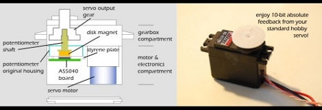
[Antonb] added 10-bit encoding to a standard servo. He’s removed the potentiometer, separated its shaft and used it to rotate a small magnet. By sandwiching an AS5040 rotatory encoder IC into the servo’s housing he can now measure the precise orientation of the servo horn. This is made easier by his tiny breakout board for the chip. If you want to layout your own PCB you can download the EagleCAD files for this device. Take a look at the final product in the clip after the break.
[yoututbe=http://www.youtube.com/watch?v=-z0Giro4R7M]


I wonder how many counts the gear backlash produces.
or just buy a digital servo…
@tim: nice contribution. If it was not for your comment, I would not have known this was possible and instead would have been pulling all my servos apart trying this hack – phew!
too bad the position data is sent back as pwm. might be too much overhead for a small controller.
oh, a little more reading and it turns out that encoder can output step/direction. a simple interrupt seems way less work and uses one less timer. there must be a reason he chose to do it this way.
They are great little encoders
http://www.facebook.com/video/video.php?v=344345270920&ref=mf
almost finished one with a pic onboard ;o)
other stuff at….;o)
http://www.facebook.com/group.php?gid=50642505762&ref=ts
Also on the servo video above my little pic18f4550 board with onboard regulator/power source, usb programming/power option, 40 pin breakout. ;o)
@CathOde The chip has multiple modes. PWM, quadrature encoder, even you can implente an analog output. You can find a board with almost all the modes here: http://www.reprap.org/bin/view/Main/Magnetic_Rotary_Encoder_1_0
youtube fail
here you are.
[youtube=http://www.youtube.com/watch?v=-z0Giro4R7M]
yeah i realized the chip has a bunch of modes. i just don’t understand why one would use pwm for this. i play with the attiny series of chips as controllers so i tend to stay away from timers for inputs. it’s a great proof of concept though.
Well PWM have multiple advantages you can control detect when the wheel make a complete turn and control the position only with 1 pin of the microcontroler. if you compare with the 3 pins needed the quadrature encoder mode…
If you’re shorts in pins is better.
The PWM can be fed into an RC filter, which will produce an analog voltage output, directly replacing the pot.
bit new but how dus this thing work and what dose it do
Practically every microcontroller has PWM capture mode which is extremely precise and requires like zero overhead. Read your datasheets.
Awesome hack, I had no idea about such sensors. Really cool.
if you set up an interrupt on the capture module of your PIC or ATMEL it is very easy to get accurate position data with minimal computational overhead.
@pete
there is no backlash since the magnet is mounted on the servo’s o/p shaft :)
@tim
the digital servo reports position data but you cannot get continuous rotation
There is something better out there than a digital servo. I am preparing a second generation board that will have the H-bridge and an ATMEGA168, all inside the servo. I will also release assembly instructions, code for PID control and schematics. The first generation boards have already been sold out.
Check my google code page: http://code.google.com/p/zosupermodified/
I will be constantly adding stuff so keep posted
Also, the PWM signal gives you the absolute position, as opposed to step/direction signals. Also, with step/direction signals, you have to be very careful with interrupt latency, as you could receive a fairly high frequency signal. Also, in the interrupt service routine, you would have to sample the direction signal, while this signal may have changed in the meantime.
@antonb OK, so no gear backlash but, the resolution is still ~0.35 or the better part of a half degree with this setup.
How critical is the centering of the magnet over the center of the chip to getting a “linear” output from the AS5040?
you should check out the http://www.openservo.org openservo! It supports the AS5 chips for position encoding and precise i2c controlled movement.
I made one of these in nineteen dickety three out of a pie plate and some dung. You whippers better start snappin!!!
@pete
I would think the centering of the magnet is critical. Saying that, provided you centre the breakout board on the styrene plate resonably well, and that the styrene plate fits tightly inside the servo’s casing, you shouldn’t have any problems. If you need more info on this visit:
http://www.austriamicrosystems.com/eng/Products/Magnetic-Encoders/Rotary-Encoders/AS5040
download the datasheet and check on page 21.
It specifies some placement tolerances as well as, the sensor’s alignment mode which one can use to ensure proper alignment of the IC with the magnet.
We’ve proved it can be done… now lets see the manufacturers making better servos and controllers!
@barryfzr: the manufacturers couldn’t care less. RC hobby business is a form of robbery.
I’ve been doing this with Melexis sensors. The Austria sensors are much nicer to interface, though.
The magnet centering does not actually matter at all, if the chip itself is centered under the shaft. Otherwise, you need to calibrate; some of the sensor chips have a built in correction table so you can be far off-center. All it really needs is that the magnet is dominant, which is easy to accomplish as magnetic fields drop quite fast with distance.