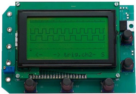
If you’ve got a graphic LCD lying around you can build this four-channel logic analyzer with a couple handfuls of cheap components. [Ronald de Bruijn’s] design uses a PIC18F4580 to sample up to four logic inputs at a maximum resolution of 2 MHz. He’s included the PCB artwork so that you can etch your own board. Having a logic analyzer around can really make your life easier, allowing you to reverse engineer communication protocols and troubleshoot your own design problems.
[Thanks Juan]


Does it support sine waves, or just square?
Well, it is a logic analyzer (perhaps look up logic signals on wikipedia) and not an oscilloscope!
Lol, I hope mrgoogfan is trolling us and not serious.
LoL
He’s from another parallel world where LOGIC signals have more than 0 and 1’s :D :D :D
@YaBa
quantum computing?
This is cool, but its sample memory is painfully limited. It wouldn’t be that hard to use a cheaper pic for the graphical/user interface and then maybe a little FPGA and memory to turn this into a monster of a pocket logic analyzer :D
Oh, and don’t for get a USB interface and some laser beams, just for good measure…
I think I might have missed the point of this project :P
What better way to learn something than to ask?
I’m sure you have successfully made mrgoogfan feel like an ass for asking. I wonder, will he continue to ask questions and learn from them, or will he live in ignorance due to a few air heads who couldn’t obviously remember that they weren’t born knowing everything, and had at some point asked questions too.
Just saying….
Ok….I hardly consider myself a novice with diagnostic tools like these….
What would be a typical case I would use something like this for, as a novice?
As in, if a circuit I designed had a flaw with I guess digital signals, how would I use this to find, diagnose, and possibly fix the problem?
where’s the analyzer part?
@clutchdude
If you can see what the digital transmissions between different chips/ports/components are, you can generally extrapolate how to communicate with the chips sending and receiving the signals.
If you read back to an article a couple days ago, someone used a logic analyzer to figure out how to send character data to an LCD in their car’s dash. There were no datasheets available, so they had to monitor the pins as they changed the settings to see what changed on the hardware when the display changed. Then, using that information they constructed their own circuit to send their own data to the display.
Old news;
http://www.elektor.com/magazines/2007/september/four-channel-logic-analyser.227976.lynkx