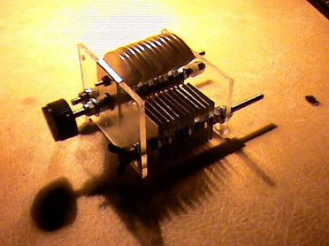
In keeping with our opinion that radio operators were the original electronic hackers here’s a guide to building your own transmitting air variable capacitors. Using some roof flashing, Plexiglas, and various fasteners [David Hammack] was able to make it work. It’s not a perfect solution but he has some ideas to make the next one better. Give this a try after you’re done tweaking your crystals and building input devices.
[Thanks Rich]


Old but good – Couple hints though… Using a parallel plate capacitor calculator, you can easily build one with the number and size of plates you need for any capacitive range. Second, don’t use roof flashing – When I tried this the most difficult part was getting every piece dead straight to ensure proper spacing – Absolute pain in the ass, use a thicker aluminum sheet, copper, or brass instead – As long as the dielectric (air) and spacing remain the same, you can substitute the plate materials without redoing your math.
So that’s the answer to a recent Hacked Gadgets name that thing contest! I remember these now from the old “Build your own FM radio” kits I had when I was a kid.
Don’t forget that this is for high power operations! Low power projects (QRP transmitter or receivers only) can get away with wayyyy smaller variable capacitors whose metal discs are much closer together!
I have been building some of these the roof flashing will work just have to be very careful. I second the use thicker material.
Read the comments…especially the ones about “linearizing”, i.e.: adjusting the shape of the blades so that capacitance varies linearly with rotation angle. A look at some old radios will show non-circular pullys, capacitor plates and gears, all designed to produce a linear frequency scale on the front panel.
@Peter-
I think you know what you mean, but your comments might be a little confusing to someone else.
“Linearizing” a rotary variable cap for linear capacitance is easy. Capacitance is directly proportional to the area of plate overlap, so a semi-circular rotor, more or less, should do the trick.
Frequency, on the other hand, is proportional to 1 over the square root of L times C, which will require you to make the rotors a sort of “half-fish” shape if you want the dial to space frequencies evenly over the span of the cap.
Another variation on the theme is linearized wavelength, a somewhat different shape again.
this is mega old.
This would work well with an Arduino
The question after calculating the maximum HF voltage on the capacitor may build at a given power and the changing output impedance, if we speak of transmitters, always is the maximum frequency, the insulation stuff between capacitor’s elements allow. It’s a profession for higher bands and/or higher output power. :-) Things are easier, if it may not be able to stand such mechanical tortures as the original parts were usually designed for (to work when exposed to vibrations etc.), especially the military-types.
I have piles of these things. I keep telling myself that I’ll use them someday, but I dunno….
Also, Yes, the plates are not circular, they are more “ear” shaped.
Good to see HAD picked this up, even though it is quite dated. Deserves a place-holder here :-)
Drone
There’s a sort of amateur radio antenna called a magnetic loop, made with a low resistance single-turn inductor and often an air-variable capacitor. With more than QRP power, the voltage at the capacitor can be quite high.
I’d love to have a way to built cheap custom air variable caps, just for mag loop projects…
There are many different solutions including cheap ones, just search for them on the net. E.g.:
http://www.laud.no/la6nca/loop/index.htm
http://www.qsl.net/mnqrp/Loop/Mag_Loops.htm
Btw. mag loops are better for receiving… there are alternatives to build for almost-no-space as well.
copper clad pc board material makes great plates for capacitors. They are very rigid and easy to solder to the shaft.