An SMD Capacitor Guide

For electronics, your knowledge probably follows a bit of a bell curve over time. When you start out, you know nothing. But you eventually learn a lot. Then you learn enough to be comfortable, and most of us don’t learn as much about new things unless we just happen to need it. Take SMD components. If you are just starting out, you might not know how to find the positive lead of an SMD capacitor. However, if you’ve been doing electronics for a long time, you might not have learned all the nuances of SMD. [Mr SolderFix] has been addressing this with a series of videos covering the basics of different SMD components, and this installment covers capacitors.

If you are dyed-in-the-wool with SMD, you might not get a lot out of the video, but we picked up a few tips, like using a zip tie for applying flux. The video starts with an examination of the different packages and markings. Then it moves on to soldering the components down.

Continue reading “An SMD Capacitor Guide”

Why Do Rifa Capacitors Fail?

Anyone who works with older electronic equipment will before long learn to spot Rifa capacitors, a distinctive yellow-translucent component often used in mains filters, that is notorious for failures. It’s commonly thought to be due to their absorbing water, but based upon [Jerry Walker]’s long experience, he’s not so sure about that. Thus he’s taken a large stock of the parts and subjected them to tests in order to get to the bottom of the Rifa question once and for all.

What he was able to gather both from the parts he removed from older equipment and by applying AC and DC voltages to  test capacitors, was that those which had been used in DC applications had a much lower likelihood of exhibiting precursors to failure, and also a much longer time before failure when connected to AC mains.

Indeed, it’s only at the end of the video that he reveals one of the parts in front of him is an ex-DC part that’s been hooked up to the mains all the time without blowing up. It’s likely then that these capacitors didn’t perform tot heir spec only when used in AC applications. He still recommends replacing them wherever they are found and we’d completely agree with him, but it’s fascinating to have some light shed on these notorious parts.

Continue reading “Why Do Rifa Capacitors Fail?”

An exploded diagram of the spot welder. Shown are the capacitor bank, trigger, 12 V relay, DC power input, power out, step up converter, voltmeter, industrial SCR module, and capacitor bank.

Hackaday Prize 2022: A Not-So-Smart Spot Welder

DIY spot welders often use high-powered components that can be a bit frightening, given the potential for dangerous malfunctions. [Wojciech “Adalbert” J.] designed his capacitive discharge spot welder to be safe, easy to build, and forego the microcontroller.

Many projects work great with just a single Li-ion cell, but when you need more power, you’ve got to start connecting more cells together into a battery. [Wojciech]’s spot welder is designed to be just powerful enough to weld nickel tabs onto a cell without any overkill. The capacitor bank uses nineteen Nichicon UBY 7500uF/35V capacitors, all wired in parallel using solder wick saturated with solder. They sit atop on a perfboard with metallicized holes to carry the high current.

[Wojciech] has detailed every step of building the welder, including changes to the off-the-shelf relay board and adding a potentiometer to the step-up converter board. The level of detail makes this seem like a good starting place if you’re hoping to hop into the world of DIY spot welders. Safe is always a relative term when dealing with high powered devices, so be careful if you do attempt this build!

DIY spot welders have graced these digital pages many times, including this one built with safety in mind, and this other one that was decidedly not.

Condemned Precision Capacitors Find New Home, Refuse To Become Refuse

Ah, the age old tradition of Dumpster diving! Sometimes we happen to spot something that’s not quite trash, but not quite perfect, either. And when [dzseki], an EEVblog.com forum user, spotted some high-precision capacitors being 86’d at their employer’s e-waste pile, [dzseki] did what any good hacker would do: took them home, tested them, and tore them down to understand and either repair or reuse them. They explain their escapades and teardown in this EEVblog.com forum post.

High-precision capacitors with RF connectors.

If you’re not familiar with capacitors, they are really just two or more plates of metal that are separated by an insulator, and in the case of these very large capacitors, that insulator is mostly air. Aluminum plates are attached with standard bolts, and plastic insulators are used as needed. There’s also discussion of an special alloy called Invar that lends to the thermal stability of the capacitors.

[dzseki] notes that these capacitors were on their way to the round file because they were out of spec, but only by a very, very small amount. They may not be usable for the precision devices they were originally in, but it’s clear that they are still quite useful otherwise. [dzseki]

Of course, Dumpster diving for cool parts is nothing new, and we’ve covered nifty projects such as this frankenmonitor bashed together from two bin finds.

Thank you [David] for the great tip, and don’t forget to leave your own in the Tip Line.

Taking A Close Look At Parallel Plate Capacitors

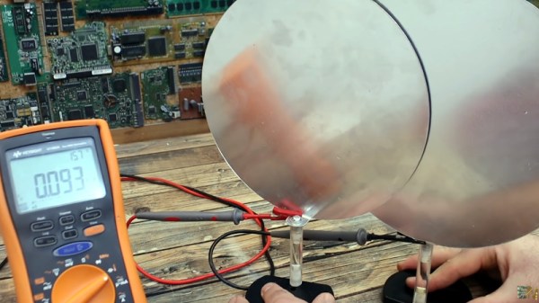
Of course, we all know that capacitors are conceptually two conductors separated by a dielectric of some sort. But outside of air-variable capacitors you normally don’t see them looking like that. For example, a film capacitor has its plates rolled up in a coil with an insulating film in between. You can’t really see that unless you take them apart. But [Electronoobs] makes some giant capacitors using large plates and does a few experiments to demonstrate their characteristics. You can see his work in the video below.

The arrangement reminded us of a Leyden jar except there’s no physical motion. He also had some entertaining footage of electrolytic capacitors exploding when connected backwards. The reason, by the way, is that electrolytic capacitors have conductive goo in them. By putting a controlled current through them during manufacturing, a very thin insulating layer forms on one electrode. The thinner the layer, the higher the potential capacitance is. The downside is that putting current in the opposite way of the formation current causes catastrophic results, as you can see.

The value of a capacitor depends on the area, the spacing, and the type of dielectric between the plates. The video covers how each of those alters the capacitor value. Real capacitors also have undesirable characteristics like leakage and parasitic resistance or inductance.

It used to be that capacitance meters were exotic gear, but these days many meters have that capability. This would be a great set of experiments for a classroom or as the basis for a kid’s science project. For example, measuring different dielectric materials to determine which is the best for different purposes.

Granted, capacitors are pretty basic physics, but it is easy to get wrapped up in using them and not think about what’s going on inside. This video is a good introduction or a refresher, if you need one. It is easy enough to make your own variable capacitors or even special capacitors for high voltages.

Continue reading “Taking A Close Look At Parallel Plate Capacitors”

How Do Capacitors Work?

If you are like [The Science Asylum], you might wonder how a capacitor can work since, at their core, they are nothing more than a gap filled with air or another insulator. He explains how in a recent video you can see below.

Of course, at DC, a capacitor doesn’t conduct any better than the insulator used as its dielectric. However, a DC voltage has to start sometime and when it does, it briefly looks like AC. The video explains it all in simple terms. Of course, if you are math savvy, you can probably get as much out of the normal C=dQ/dV equation.

If that doesn’t speak to you, the explanation in the video about charges will shed some light. He even shows an animation of the classic “hydraulic model”, which is helpful to develop intuition about the process.

Continue reading “How Do Capacitors Work?”

A close-up view of surface-mount components on a circuit board

Smaller Is Sometimes Better: Why Electronic Components Are So Tiny

Perhaps the second most famous law in electronics after Ohm’s law is Moore’s law: the number of transistors that can be made on an integrated circuit doubles every two years or so. Since the physical size of chips remains roughly the same, this implies that the individual transistors become smaller over time. We’ve come to expect new generations of chips with a smaller feature size to come along at a regular pace, but what exactly is the point of making things smaller? And does smaller always mean better?

Smaller Size Means Better Performance

Over the past century, electronic engineering has improved massively. In the 1920s, a state-of-the-art AM radio contained several vacuum tubes, a few enormous inductors, capacitors and resistors, several dozen meters of wire to act as an antenna, and a big bank of batteries to power the whole thing. Today, you can listen to a dozen music streaming services on a device that fits in your pocket and can do a gazillion more things. But miniaturization is not just done for ease of carrying: it is absolutely necessary to achieve the performance we’ve come to expect of our devices today. Continue reading “Smaller Is Sometimes Better: Why Electronic Components Are So Tiny”