The Intelligent Ground Vehicle Competition (IGVC) is the precursor to the DARPA Grand Challenge, and in many ways it is just as difficult. We have the pleasure of being at the competition this year with the Tennessee Technological University Autonomous Robotics Team. The teams at the competition pull off some amazing home-brew robotics, so we’ve decided to do a short section on some exemplary robotic hacking each day of the competition.
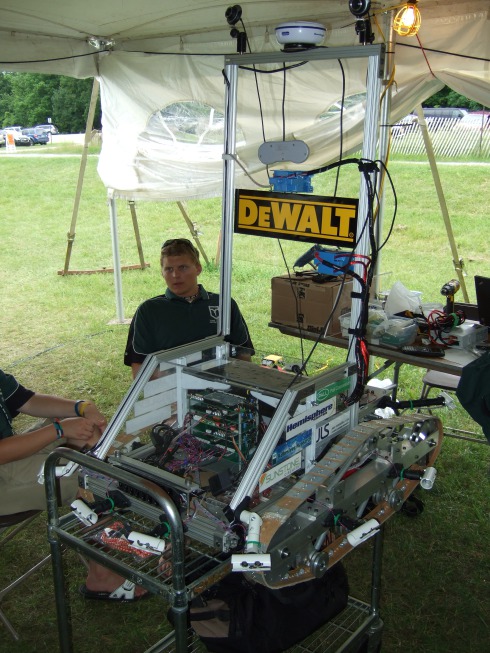
Today’s robot comes from the York College of Pennsylvania. The robot, dubbed “Green Lightning”, features an impressive set of custom made hardware.
We interviewed the team, and got a pretty thorough rundown of their robot with pictures after the jump.
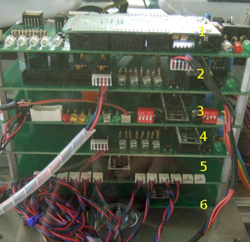
The spinal cord of the robot is this custom built beauty.
It consists of six layers, each with a specific function. The boards were designed by the team and fabricated by Sunstone Circuits. Each layer except for the top has its own teensy++ unit, programmed in C, providing an SPI interface to the hardware it’s designed to connect to. The first layer has an Arduino Mega programmed in C on it. The layers communicate with the Mega through an SPI bus running at 500Kbaud. The Mega processes the information and then communicates to a computer through a 1Mbaud usb serial connection.
The remaining five layers are each designed to interface with a specific section of the robot’s hardware. The second layer communicates with a Wheel Commander from Nubotics, simplifying the robot’s motion controls.The third layer is the interface to the robot’s emergency stop. The rules require that there be a visible hardware e-stop on the back of the robot and a wireless remote e-stop. They solved their wireless e-stop problem with a zig-bee module that connects to the robot through this layer.
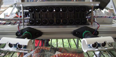
The fourth, fifth, and sixth layers all connect to the robot’s sensor groups. The fourth layer is the interface to their gps, mounted at the top of the robot. Most gps units communicate with simple serial and it’s pretty elegant that they managed to save a usb port by adding a board. The robot has nine Sharp 2Y0A710 distance sensors acting as a short-range bumper for obstacle avoidance which all connect to the fifth layer. The final layer is the interface for 10 long range sonar sensors located at compass points around the robot.
The robot also has two USB Web Cams for line and object detection mounted on the mast. The AI and computer side hardware interface is programmed in a mix of C and Java. The AI follows a reactive model instead of a mapping/planning one which has been proven to be very effective in this competition for many teams.
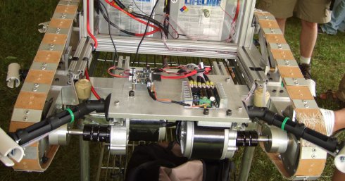
The frame, track, and drive train were custom built by the team as well.
Here you can see the back of the robot where the drive train, Wheel Commander, and two SaberTooth motor drivers are.
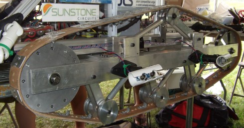
A side shot shows their track system. They modeled it in SolidWorks first and then fabricated everything including the belt in house.
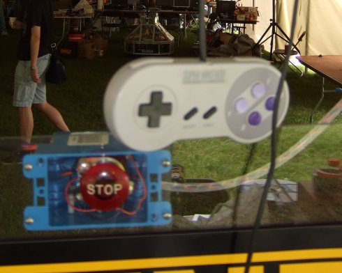
In the end the robot cost them around $5,200 after discounts which is pretty impressive considering its capabilities and that some of the robots at this competition easily break $50,000 dollars. It’s a prime example of what good engineering and home-brew magic can accomplish. We’ll finish with a shot of their manual control system.



Sound like fun
Sounds like fun
Please hire staff who can write competently if the primary focus of your enterprise is on publishing what your staff write.
If it’s supposed to be possessive, it’s just I-T-S. If it’s supposed to be a contraction, it’s I-T-apostrophe-S.
IT’S NOT HARD TO GET IT RIGHT.
Is it just me that thinks 6 MCUs AND a PC is a bit overkill for this? I mean (assuming the description is accurate), a WHOLE board and processor, just to interface a serial GPS? Elegant? Really?
Also, a whole layer for emergency stop? This too seems a little unnecessary. Obviously the e-stop needs to be fail-safe, and respond quickly, but a whole extra micro just to kill the power?
I may well be wrong, if so I apologise, it just seems to me this could be done with way less hardware, especially as it’s being hailed here as “a prime example of what good engineering and home-brew magic can accomplish”. Meh. /rant
@kernelcode
It would allow dev and test time to be split up across the team that way, without the need for duplicate hardware. The teensy++ has a AT90USB on it. and is $28 before any discount they got. It is probably a bit of verkill, but at least the parts are the same, easy to get and simple to get back up and running.
@kernelcode
A couple of things about your post. The E-stop rules for IGVC are very stringent. I believe this is a sort of necessary evil.
Also, with regards to overkill ;) the teams run image processing software on the robots in order to sense things like objects or lines on the field and other such things. I don’t know if I would call it a prime example of home-brew engineering, but it is super cool.
@kernelcode
I started gandering at the rules.
–quote–
“… Vehicle E-stops must be hardware based and not controlled through software. Activating the E-Stop must bring the vehicle to a quick and complete stop.”
–end quote–
The estop would have to be a separate system to be legal.
As far as the separate layers I think this would allow faster processing and multitasking for task specific applications. For example . . . because the speed is govern to 5 mph and knowing position is important, why risk other tasks and sensor readings for encoder reading? Knowing your position is just as important as knowing your speed or knowing if there’s a wall in front of you. The separate layers allow the particular layer worry about all of the input of that layer and processing to get a usable output. EG reading all of the voltages from the proximity sensors and converting it to inches instead of all of the software worrying about voltages.
Thanks for your replies guys!
@Cynyr:
I guess the need to develop the subsystems separately is fairly obvious, and I can see the merit in not losing all control if one of the boards fails/crashes, good point.
@Dantheman2865 RE image processing:
That’s running on a PC though, and should not increase the need for additional external components. 2 Webcams and 2 USB ports, job done!
Agreed, pretty damn cool!
@drake
I didn’t read the rules I will admit – if they say the E-stop must be separate, it must be separate!
With regards multitasking: They have a GPS, 2 Webcams and 360 degree sonar, why would you need to read encoders?
They also have a full PC, why not do the number crunching on that, send it raw analogue data over USB?
Anyhow, I’ve never attempted anything on this scale, and have no reason to believe I could do better. It just seems like they may have a whole lot of extra processing power.
Awesome! IGVC gets some recognition! I’m on the Missouri S&T robotics team and our robot Aluminator is there right now. I went last year and it was a lot of fun, but this year I couldn’t go because of my job.
The E-stop has been an issue for us, our motor controllers (Elmo Motion Control system) have integrated E-stops but it isn’t hardware based, last year we used an AVR to control a huge monster relay but we tacked it together at the last minute and it failed during qualification. This year we actually designed an Xbee based remote E-stop so hopefully it works better.
We do have a full PC (Core 2 Duo mini-PC) running custom image processing software on the Ubuntu operating system. Our input source is 3 Logitech webcams and one Videre stereo Firewire camera for obstacle detection. The webcams all render together for a birds eye ground plane used for line detection. We are also considering a servo powered rotating mount for our stereo camera so we can look in different directions.
@kernelcode
GPS is fairly slow compared to an encoder. With gps you have to wait for a signal to return from satellites and then do some processing to determine position speed etc.
Then theres the issue of GPS drift where theres a slight inaccuracy in the coordinates. It could be sitting still but the GPS will say its moving.
Finally with encoders you can accurately control speed, position, and rate.
To make matters worse as far as processing, in order to properly use a regular quadrane encoder you will need interrupts. And a massive amounts of interrupts will slow down all of the other code running.
All in all, when doing robotics, reading sensors faster is better.
“hardware interface is programmed in a mix of C and Java. ”
Why do they need 2 languages?
I bet the code of this robot is a bunch of IFs if something is in distance x turn or stop or go backwards.
“layers communicate with the Mega through an SPI bus”
Why are there layers at all which have to communicate? Why can’t they just put them to one pcb.
So, let’s clear a few things up just to let people know some info about how everything fits together. First off I’d like to say thanks to the author of the article cause they really gave us some good publicity and showed off what we did very well and for that we are very grateful.
To address the e-stop concern, yes, this absolutely had to be a separate system in order to even qualify for competition. These rules are very stringent and if not met you are not even allowed on the practice course. From an engineers standpoint think of it this way, if it was on the same processor as everything else would you want the vehicle to stop before hitting you at five miles an hour or be delayed because of a “toggle LED” command and break your leg? And believe me, it would cause its heavy and moving quick.
The software was programmed in multiple languages for a number of reasons. C is very simple to program the microcontrollers in and also executes very efficiently. Also, programming in Java for an embedded system is difficult as compiling for java is typically done using JIT compilation. This would overwhelm an embedded 8-bit processor. Java however does run well on a multi-core pc which we used for image processing and navigational algorithms. And doing image processing on an embedded system would be near impossible as the processor would not have the necessary resources to accomplish this task in a timely fashion.
And no, the code for these robots is not a bunch of IF’s, it is code designed by computer science majors and computer engineers who have studied algorithms and considered many possibilities. If fact our robot created a map of it’s environment to navigate.
There are layers because each subsystem is created by a separate student as their project and while it could be programmed on the same hardware and merged later, why not have a common communication protocol you know you can use and then just work off a common platform which acts as a “plug-and-play” system. In this manner our system was built by individuals, combined in the end when it was time, and if any system were to fail or be incomplete the central controller would shut it off and compensate with what is has and continue. Besides, the way we designed it allowed for parallel processing with a central processor simply collecting data and throwing up to the PC which made the decision as to how to act, send the decision back, after which the central unit communicates with the required hardware to execute what’s needed.
There’s more I could say but in short it’s a hard competition which requires hard work and many considerations. We chose to think economically and outside the box using handmade components. In the end we had a well mad secure structure made by an interdisciplinary team. And if you think it’s overkill you should see other teams. Anyway, thanks for looking at our project. We worked hard and I think we did well.
@ ycp
First of all: congratulations on your robot. Automonous vehicle design is no small task, and your team got something out the door which was not only functional, but seemingly fairly rugged as well.
This takes the professionalism up a notch from some robots/hacks I’ve seen which look like they have a 90% failure rate even with frequent operator intervention.
I’ll be leaving soon for a robotics competition myself, so I can appreciate the reasoning behind some of the points you raised.
Please try and be a little bit less defensive. It hurts your professionalism and comes off as insecure.
If you’ve ever published on social media before you should realize that armchair quarterbacking/sneering goes with the territory most of the time.
The ammount of embedded systems at first impressed me as slightly redundant/overkill, however I don’t presume to know the entire list of design constraints & engineering considerations which ultimately lead to the path you took.
For instance in my robot: we have a number of PIC based microprocessors being controlled by a microcontroller which interfaces with a laptop.
It may have been possible to make a single do-everything board but it begs the question: why bother? The current solution gets the job done and we have more pressing concerns than making a proprietary board for bling factor.
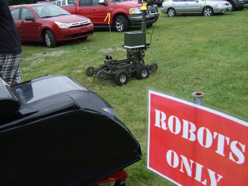
I have that same sign in my yard. “Robots only”
I’m so bummed! The first year in 3 that I was unable to attend IGVC with my club and HaD shows up! Very cool, sorry I’m missing it. :-)
@CalcProgrammer1: I’ve been developing my club’s E-stop for the last two years and learned some very important points: Avoid 2.4GHz like the plague… Our E-stop this year uses the XBee900 which is in the 900MHz range and uses spread-spectrum hopping to further withstand noise in the environment.
And a shout out to my club, RIT Multi-Disc. Robotics Club with AMOS 3: Congrats on qualification and best of luck this year guys! :-)
I like and I dislike. Where I dislike is the multiple stacks deamd elegant. I once did a project, and had multple pics, then I just swaped it all out and used a pic32 and went multi threaded. Another project, I just used a 44pin pic for I/O and used a laptop for the rest.
Another reason to run a separate stack of systems like this is that it can cut costs in manufacturing.
Instead of having to route traces for all the IO and processing on one integrated board, you have the opportunity to simplify on each break out board.
I’ve seen this type of design used in aviation applications as well, allowing the replacement of a single sub assembly rather than having to rework the whole part on the spot, or replace it entirely.
This allows the tech working on the system to just replace it, check that it’s working correctly after the replacement, and put it back in service.
In this case, having the added constraint of multiple people building the different systems (sounds more and more like an aviation, committee designed system…) this makes even more sense.
All you have to do is have a standard that they know to interface to the primary CPU with, as well as a requirement of what their system is expected to perform.
If you manage to avoid the government style result of this (budget over runs, revisions and reductions of specs to even allow the finished product to “meet” the specs…) then the finished products are assembled, tested, and put to work.
Quote: “…that armchair quarterbacking/sneering goes with the territory…”
Translated: “Those who can’t, moan about how they might/could/would/DIDN’T make it better.”
Meh on the whiners, and thumbs up to those who go out and build.
Does nobody understand the idea of REDUNDANCY? If one component fails, the robot is still capable of completing its task. Look at them as backups. When it comes to top-end competitions, having more than one system in place to accomplish the goal can be viewed as additional chances.
Look at it this way, every single one of you that has driven an automobile would hate them if it weren’t for redundancy.
Every system employed by the US Armed Forces or even the local PD, has some form of redundancy. The multiple options, gives the system something to continue with in the event of a failure.
Excellent work to everyone who is attending or contributed! Can that thing push a lawnmower? I have 4.5 acres to mow….