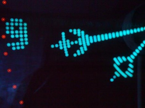
[Kizo] built an extraordinary persistence of vision clock. The design uses a PC cooling fan to spin the propeller-like PCB. As it goes around, a hall effect sensor synchronizes the illumination of the LEDs to draw the display. Power for the rotating electronics is transferred wirelessly via a transformer on the base and coil on the spinning board. The final version uses an ATmega324 microcontroller running at 20 MHz and has an IR receiver for changing the settings. The 3000 lines of code bring a lot of bells and whistles, including a menu system with a huge amount of settings from tweaking the clock display, to font selection for scrolling messages. Take a look at the demo after the break. The double-sided board looks like it’s pretty difficult to etch at home, but as you can see from the forum post (translated), [Kizo] did a great job on this build from start to finish.[youtube=http://www.youtube.com/watch?v=Q1saYuGyw7A]


Wow that is amazingly well done! Make a kit :)
that is amazing
Wow, that’s amazing – The work on the interface, especially the slot and text entry looks like a lot of fun.
Beautiful clock, very cool interface. And I particularly like bladerunnerish colours, even though probably this is a camera artefact and irl the colours are way off.
Excellent work, really nice product!
This is truly fantastic work, it makes me want to build one myself!
Way to cool! Any chances we can peek at the schematics?
yea that is tight
This was very nice.
Holy shizzle…
…that guy’s like a god of interface design.
I love it how he solved the power supply problem on a rotating connection. No connection.
Cool! This one use hall sensor to synch LEDs
Thats just awesome!
Now I want to make it too :P
Great design. I’ve been thinking lately about a way to use one of these in my car’s instrument panel for a cheap, expandable digital tach. More useful for me than most because it’s becoming an EV (lots of battery/pwm controller data to display) and the only other system as flexible costs close to $900.
An amazing POV project for sure!
Brad
Awesome work indeed.
I was wondering if anyone could find more info about the transformer used for power transfer at the moving side. I see there’s a post where he’s talking about having problems with initial design and then something about low dropout regulator and flyback converter. Sadly i can’t make much sense of what google translate is showing.
future product developer right there
nice clock, wonder if someone can make one using reused HP printer glass, LEDs and motors?
another thought, use a brushless motor mounted behind the glass with a magnetic coupler to spin the assembly for a totally enclosed setup..
something like this could be useful for displaying video on the cheap?
That is amazingly kickass, and he should sell kits. The only problem I see with it is that it spins. Where there is spinning there is noise…
Great job ALSO LOVE THE DRUM AND BASS track :P
Very cool :D
That looks fantastic !
Can’t find the code though 8( , anoyone see it ?
Entry for dragons den this.
That’s rubbish, and I know little kids who could do better. In their sleep.
Just kidding! It seems sufficiently nice that even the trolls aren’t bothering to attack it! :)
Has anyone seen a oscilloscope type POV visualizer like this? i think it would be cool to be able to just have your “clock” turn in to an instrument when you need it
Absolutely, astonishingly jaw-dropping. I would buy this for three or maybe four figures (any time I leave the classroom and have that kind of cash). Could the author provide a difficulty rating, 0-10 where 0 is stupid-easy?
@grenadier: you could get a really big pabst noiseless fan (they’re not noiseless but they are very quiet when balanced properly) or you could use something big, like a Hunter no-contact ceiling fan motor. They’re sufficiently quiet that they are almost not heard by even myself (I don’t see too well, but I hear very, very well)
hi, this is a nice project. i want to make it. so plz. send me the parts list, circuit design, and making process. thanks
I am looking for the code for this, anyone have it? Please and thank you!
This is cool. I am making it. does anyone have the code and a list of things requires to make it. Or some form of an instruction manuel
Please and thank you :)