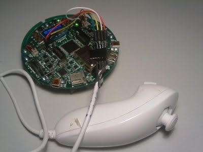
[Martin] got his evalbot recently and wanted to try controlling it with his Wii nunchuck. After some trial and error, he finally got it working. He’s shown that controlling the bot with the nunchuck was actually pretty simple, but there are some other tips that could be pretty helpful in the process. One was the fact that the point where he’s taking power for the nunchuck could easily be shorted on the motor. He wrapped his in tape, but we could see this little bug pestering us for a while before we figured out what it was. You can download his code and see his build process on his site. Be sure to catch the video of it working in both accelerometer and joystick mode after the break.
[youtube=http://www.youtube.com/watch?v=WpGJNhKFiE8&w=470]


Just to let you know 3.3V and I2C are available on the two 20-pin headers (which are also compatible with the TI RF dev-modules).
Cheers.
Its pretty cool!
-Ashish Ahuja
i just got my evilbot like 2 days ago and i cant wait until im not sick so i can hack the hell out of it
did anyone elses come with a bunch of extra parts? O_o?
@biozz
They give you a few extra of the tiny parts as you may lose them. Its mentioned in the assembly guide that they may give you extras.
I ended up with 5 extra screws of various sizes, 1 Nylock nut, a grub screw and an end cap.
Excluding the extra bits above, you should only be left with the tool, extra AA battery and the USB cable. There shouldn’t be anything else.
They cancelled my Evalbot order :(
Sadness.
@Shadyman
Huh? How come? TI said that they’d fulfil all the EvalBot orders that had been processed even though they were technically invalid due to misuse of the coupon code.
I ordered one and it arrived last week with no problems at all.
Mine arrived 2 weeks ago, too. It took more than a month to ship and then it was overnighted LOL. The box was huge, too.
Did anyone else have trouble putting on the wheels. My wheels don’t seem to fit on the motor axle(just a little too small).
@DarkAnt
See the Documentation Addendum
http://focus.ti.com/lit/ug/spmu164a/spmu164a.pdf
“Due to plating tolerances, it might be difficult to fit the wheels to the motor shaft if the wheel is assembled first. Instead, fit all three wheel pieces to the motor shaft before inserting the set-screws.”
@DarkAnt: Yup, same problem here. I reamed them out slightly with a step drill (just the bit, by hand) and they eventually went on OK.
The 3 pieces of each wheel went onto the axles fine here. I need to get some clamps though to redo them as there is a gap between the pieces. Its hard to get them completely flush when putting in the grub screws.
Thanks dyanoshak and Jake H!
Samtec.com will send out samples of the connector needed for the EM ports. It’s part number SFM-110-02-S-D
I’m using these to breakout the SPI and I2C buses to a breadboard. Used hardboard, nylon spacers and 4-40 screws to build a platform 3/4″ above the robot.
Massive thanks to Martin for posting the source and his Eclipse project files — I was able to compile this code locally and get my evalbot OLED screen to say hello. The display code seems buggy (screen shows random junk) when writing more than one line out to the display, but I’m not one to complain!
I had to piece details from various places to get the toolchain (use CodeSourcery G++ lite) and openocd up and running — If time permits and/or I can refine the firmware flash process with openocd (e.g. automate it) then I’ll write up a tutorial for your pleasure and/or disdain. I recommend you start by creating a virtual machine (OpenBox, not the OSE version though!) and install Ubuntu to isolate the tools from your daily environment.
Just got my evalbot the other day, and im in australia. very nice piece of kit, and i also ended up with spare bits.
hi.i need some help with the evalbot. i want to find the ports where i can send some signals and see the response on osciloscope.i see there is some ports PJ2,3,4… but i’m not sure.can someone help me with this?