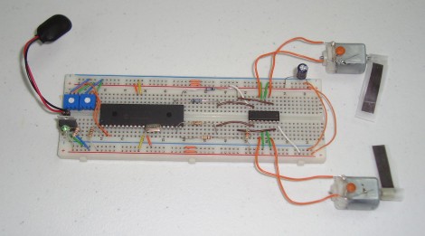
So your electronic hobby skills are coming along quite nicely but you’re not very comfortable doing more than blinking a few LEDs. Now’s a good time to try something new by driving a couple of DC motors.
You probably know that you can’t just hook these up to the pins of your favorite uC and call it good. The motors draw a lot of current (especially if they’re strained in lifting a heavy load) which would burn out your logic circuitry. Add to this the excess induced current that is generated when a spinning motor is shut off and you’re going to need a control system that can handle these dangers.
Enter the h-bridge motor driver. [Chris] has guided us through the process of building and using a H-bridge in the past. This time he’s using a motor controller that has four half H-bridges built into it. He hooks up the SN754410 to two motors, giving him speed and direction control for both based on the duty cycle of a PWM signal entering the chip for less than $2.50. Check out the video after the break for an overview of his methodology, then work your way through the multi-page post that he recently published.
[youtube=http://www.youtube.com/watch?v=UzdSUYf7SLo&w=470]


Scorpian?
^
I was thinking that!
I guess that is fine if you are only going to run 1A. The switching times aren’t great , using it for PWM speed control would give excessive ringing. You would get farther with some transistors or logic level fets. They can be placed in parallel if you need more amps.
Cool scorpion driver.
I saw no mention of clamping diodes in this post or in the linked article. FYI to those working with motors, relays, solenoids and so on: always use clamping diodes because the changing magnetic fields in coils can produce unexpected and unwanted high-voltage spikes in your circuits. Even if you’re using the popular SN754410-compatible L293D driver chip, which has diodes built in, design external ones into your circuit to be certain your micro is protected.
totally thought scorpion the instant I saw it
Good tutorial.
Is he using the C18 compiler?
@kuy or any one who knows this
sorry for my ignorance but clamping diode or free wheeling diode?
@ patrick
There are two similar soloutions for dealing with back EMF. I think kuy meant clamping network which is two diodes in series one being reverse biased.
The other is the free wheeling or flywheel diode which is just a single diode in series that is reverse biased.
Either way kuy is right in saying that external back EMF protection is necessary. Along with some appropriate sized bypass capacitors. A lot of higher amp / voltage designs use optoisolators to segregate the logic from the motor controller circuitry.
a correction in my post above.
The flywheel diode sits parallel with the load. The clamping network also sits parallel with the load.