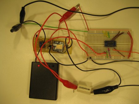
When [Kerry] wanted to measure some very small resistances very accurately he did not want to fork out the big bucks for a high end multimeter or a mico-ohmmeter, so he decided to build one himself. Measuring resistance is a simple enough concept, it directly implements Ohms law (V=IR). The problem with very small resistances is that when you apply a sensibly sized constant current to the load, the voltage to be measured is too small for conventional multimeter.
To overcome the problem [Kerry] designed a constant current source of very high accuracy using the AD8276 unity gain difference amplifier and the AD8603 high precision opamp. Then to boost the voltage across the load he used the LMP8358 programmable gain precision opamp, this allowed him to easily change the gain for different magnitude resistance, the circuit diagrams are all available on his site. Finally he used four point probes to eliminate probe wire resistance errors, ending up with the ability to measure small resistances with very high accuracy.


Afrotechmods has the best (yes the best) tutorial of 4-wire resistance measurement.
http://www.youtube.com/watch?v=0vMvCVyOp9g
That is an excellent tutorial for Kelvin measurement. I remember when I was just starting out in my career… I’d just got some new prototypes for a controller I’d designed, but they didn’t work. Lots of shorts under components and so on. The old timer (my eventual mentor) taught me how to find where the shorts where by using Kelvin measurements to measure the voltage drop of the power nets and then “home in” on the short by moving the probes one at a time until I could get the lowest reading. It was pretty damn cool, and something I never forgot.
If it were me, I’d make a bridge with a piece of e.g. nichrome wire. Slide a probe along the wire and find the null point.
Excellent engineering. However, his 4-ponit probe looks like it doesn’t prevent errors from the clips.
That’s why you don’t measure the clips. Your meter should be touching the component, not the clips. It’s potentially only a couple of mV, but when you’re trying to measure mOhms, these things matter.
I dont know if it gives an exact measurement, that values of resistance are really small compared to any junction, wire etc. connected to the device under test.. also the thermocouple effect may be appreciable.
This is also useful to read strain gauges. Thanks for the tutorial!
In a pinch you can get very close with just a LM317 and a single resistor. I use a 12.4 ohm and setup the LM317 for constant current. That gives about 100mA and is very good into the mV range (and easy to do the math in your head). I don’t even have a power switch on mine. It draws power when I put the probes on the board. I also use alligator clips and shielded cable to have distinct current and sense paths.