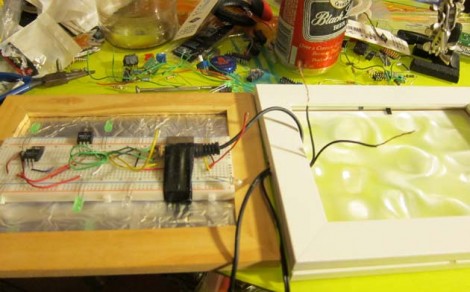
If you want an easy project to spice up your next party, chances are you already have parts on hand to throw together [Mikerbot’s] quick and dirty VU-meter lights. The circuit he designed uses the audio input to trigger the base of a PNP transistor, toggling power through a string of LEDs. He’s using four lights for each of the stereo output signals, making them pulse with the music as seen in the video after the break. The circuit is built on a breadboard, and housed in a picture frame with a less-than-impressive diffuser (we think that’s always the hardest part… check out the Heavy Frost used in this project if you want something that works really well).
There are some VU meter chips out there that will really augment this concept. But one improvement might be to throw in an amplifier chip like the LM386 and a couple of potentiometers so that you can dial-in the sensitivity.
[youtube=http://www.youtube.com/watch?v=jFnrBWQRTsY&w=470]


Not half bad!
needs more seperation. make 8 channels but only use 4 to give a better seperation between them for a nicer look.
I don’t quite get why a breadboard was chosen for this. I love breadboards and can never have enough of them at home, but for permanent projects, they just won’t cut it.
That said, I was wondering about the audio connection. I see the audio ground is directly connected to ground–is this safe for the equipment involved or should you try to use a transformer?
The audio ground is technically not supposed to go to circuit ground all the time, but is often used in that way to simplify things.
It really makes a negligible difference if the ground is attached like that on the destination end of the audio cable versus the signal end. The signal end can introduce all sorts of noise into the audio.
this is the second article this week ive seen where TIPxx transistors and leds are used together WITHOUT resistors… hmm…
then again i didnt read through the whole thing, and ive seen how good this circuit works WITH the resistors… so awesome project in that respect, and your idea for puting it in a pictureframe is high on the W.A.F. / Gf.A.F. and looks sweet!
FYI: a 9v battery would probably have enough resistence to work this WITHOUT blowing the LEDs after 10 mins: 100 ohms / stereo LEDs = 200ohms / LED string, which is about right anyway. :)
… that other project i saw this week had it on computerPSU and no resistors… => smoking_parts??;
Diffuser is not a problem. Rosco and Lee have a number of different ones with different levels of diffusion. Just put a sheet of what you want under the glass of the picture frame.
http://www.rosco.com/us/technotes/filters/technote_3fv.cfm
You’ll find this stuff in places that cater to theatrical lighting or filmmaking. For those in the states this is a good place: http://www.bhphotovideo.com/
by divided by i meant doubling the current and thus doubling the voltage drop of the batters’s internal resistence, (ohms law) just in case i typed it a bit short-hand, so that it works out so as if seperate 200 ohm resistors (per string) on a high-power-reg.d PSupply
I think the schematic has the polarity of the 12V input reversed.
I think it just has the LEDs the wrong way around :)
Perfect for a party where we’ll be drinking Black Label!
Wax paper from the kitchen works as a good diffuser. Just crumple it up and then straighten it back out again :)
Couldn’t you throw some various resistors in there to get more separation between LEDs? Like passive crossovers…