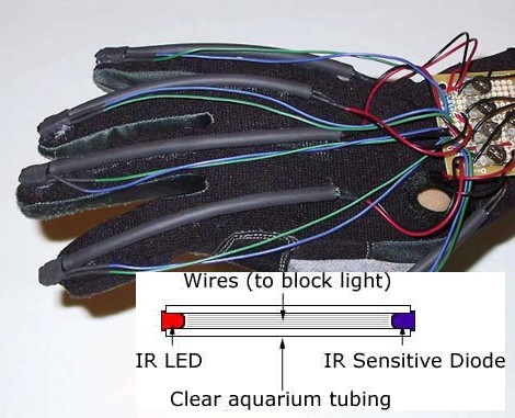
[Joel] dug up this hack that he pulled off over ten years ago. It’s inspired by the Nintendo PowerGlove, and uses flex sensors to react to movements of your fingers. The interesting thing is, he built these optical flex sensors himself.
He likes to say that this is a ghetto fiber-optic setup. The inlaid diagram above gives you an idea of how the sensors work. An IR LED and infrared diode are positioned at either end of a piece of clear aquarium tubing. When the tube is flexed, the amount of light that makes it to the diode is diminished, a change that can be measured by a microcontroller. [Joel] found that he could increase the resolution of the sensor by adding something to the center of the tube, blocking the light when not straight. In this case he used pieces of scrap wire. The outside of the sensor was also wrapped in shrink tubing to keep ambient light from interfering with measurements.
He uses a trimpot to tune the sensors but we wonder how hard it would be to add a calibration algorithm to the firmware?


this is a genius idea!
i absolutely have to try that.
nice one had!
Using a MCu as dac to read the values, you can remove the trimers.
Just put a button to calibrate. After push the calibrate, open up and close your hand during a few seconds. Register de max and min of every sensor and use it to scale the response.
Quick, easy and very reliable.
That makes perfect sense. But to be honest I have no idea why I didn’t end up doing that.
Might have something to do with inexperience and me being a visual arts student back then (now a software developer)
“I threw in lengths of scrap wire to interfere with the the IR transmission”
How does scrap wire interfere with IR transmission?
It’s physically blocking the light?
Yes.
Sometimes trimpots are the way to go. Any software calibration is a reduction in dynamic range. If 30-50 were considered in-range values then you’ve only got 21 good values to use. Where as if you were to adjust gain/offset with trimpots you’d have much better resolution because you could in theory use the entire range of the ADC.
Cheap and works. Keep in mind though that it’s nonlinear – you get some gradation but the resulting interaction is still pretty coarse.
Actually, according to the link, the readings are “more or less linear,” and he has potentiometers on each sensor to fine-tune the readings. If you set your base and max voltage right, coarseness of signal shouldn’t be a problem, even if your graph is less of a straight line and more of an S-curve.
I, too, think I’d like to try this.
Also, check out the 3D-printed animatronic tentacle on the same site.
Optical fibers were the bend sensors in the VPL data glove created by Tom Zimmerman back in 1982. The CyberGlove from Virtual Technologies/Immersion Corp also used optical bend sensors. One of the tricks (if i recall correctly) was the optical fiber bundles were scored slightly at specific intervals. Bending the fibers caused them to loose more light, giving better response…. and shorter overall life.
Cool to see a DIY hack recreating the technology!
I think I might have gotten the initial idea from that. But didn’t know about the scored fiber bundles. However, 11 years is a long time to remember some details :)
“An IR LED and infrared diode”
should read
“an IR led and IR phototransistor”
I remember seeing plans similar to this in a Virtual Reality book in the mid ninties. That one used LDR’s but the same concept.