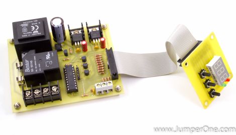
[Phil’s] parents grow their own organic food, but the harsh Ukraine winters make storing it a difficult proposition. Since it can drop to -30°C on occasion, they asked him to find a way to keep their storeroom at around 5-7°C above zero. He decided to construct his own programmable thermostat to keep things in check, and has been documenting the process as he goes along.
The thermostat uses a DS18B20 temperature sensor to monitor the room, and the logic is handled by an ATtiny2313. When the temperature dips low enough, the ATtiny triggers the room’s heater via a standard 240v relay. He can check the current temperature via a small 7-segment display mounted on the control board, which also contains three microswitches for controlling the heater.
It looks like a pretty solid build so far, and while he hasn’t finished coding the thermostat just yet, [Phil] says that those details are forthcoming. He has published a schematic however, so you can get a jump start on building your own if you’re looking to warm things up this winter.
Continue reading to see a video overview of the thermostat’s design.
[youtube=http://www.youtube.com/watch?v=tsembYXfF7c&w=470]


Nice build.
His accent reminds me of.. “I know…..how to count….alllll de way to schfifty five.” lol
Neat project!
I think it’s better to have the relay contacts separate, not connected to the mains – more flexible as you it would be galvanically isolated and you could then switch any thing with the realy on the PCB.
Actually in this case I would have the PCB relay actuate an external contactor. Then you can put any load you like on the contactor. There is no way the traces on the PCB could handle a larger load, especially not 30A.
Also run the relay straight from the unregulated power. Less power dissipation over the 7805 and the relay don’t really care.
Not to diminish this work, and I certainly could not do it, but wouldn’t a comparator and a pot work for this?
Uhhhhhhhhh…………………………………………………………
How about a 5 dollar thermometer and a low temp thermostat? What would that cost, like 15 or 20 dollars, and take 20 minutes of your time?
I very much like this build.Although the concept isnt pretty new, the high marks are for the execution.
Some if the things I might add to the project
1) Optically couple the mains and MCU side so that users dont get a shock is something goes wrong
2) Build a fan inside the enclosure which allows more even circulation to the temperature sensing chip.It being very close to other elements in the PCB might trigger spuriously.
he said the temp sensor will be connected with a cable ~10m away, so – no need for a fan for that…
Adding a fan might not be the best idea for the temperature sensor. I’ve used thermocouples for room temperature sensing in the past and found that even a breeze from someone walking near the sensor will give you lots of spurious readings. For thermocouples I found that keeping the tip in a sealed plastic jar of isopropyl allowed me to get a good average and avoid detecting the peaks and valleys induced from such breezes. I’ve never used this type of sensor but I imagine that a fan blowing across it would really throw things off. I would just go with vents in the side of the box instead.
Awesome build. Love the display and overall quality. Well done! Methinks this chap might do this kind of thing for a living though…..
Tip to thermostat buildes: DS1620 can be programmed to temperature you want and has logic outputs when temperature is high/low.
I’ll be honest I never watched the video, but I would use an SCR like this to provide optical isolation and and you can pulse the heaters for better control.
I notice the linked SCRs are pretty expensive but you can get these for closer to $10 each if you shop around…
Sure, it’s not a new technique, but that was a GREAT video in terms of documentation! I’ve been meaning to update my own project portfolio with documentation HALF as good as that. I mean, who ever makes two levels of block diagram for their thermostat, that’s just awesome. Good job!
I’m in Ukraine as well but it’s super expensive to ship from mouser or digikey to here. Phil, if you read this can you tell me where you source your electrical components?
I’m not good in building this type of things but I can try. I need to build a thermostat for our house so I’m really glad that I’ve found this video.
–Fiona S.