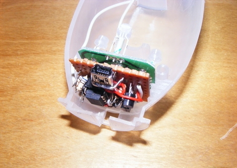
[wejp] picked up an IKEA SPÖKA night light, but he wasn’t entirely impressed with its functionality. Pressing the top of the ghost’s head causes it to cycle through a few colors, and pressing it a second time locks it into displaying the current color until its tapped again. Inspired by this SPÖKA hack which used a different version of the night light, he tore his down to see what he could do with it.
Upon stripping off the outer cover, he found that the internals were considerably different than those found in its glowing brethren, though they were perfect for what [wejp] had in mind. He removed the rechargeable battery pack as well as the controller board, which sits on a PCB separate from the LEDs. He replaced the stock micro with an ATtiny25, which he uses to give himself a bit more control over the light display.
He couldn’t quite cram all the functionality he desired into the ATtiny, but he planned on powering the light using his computer anyhow, so he installed a small USB port in the back. When connected to his PC, the SPÖKA can be controlled more precisely than when it operates alone.
Unfortunately there’s no video available of the SPÖKA light in action, but there are plenty of images available on his site.


Very nice throughout write-up! The wow-factor of the project itself is limited to a few leds and a button, but there are nice possibilities, such as using it as a notification acknowledgment device (nabaztag-like). Plus, it doesn’t look hacked, so that’s very cool!
Could make a great load indicator for a server. Slowly goes from purple to red indicating server demand. With the flash ability if there was an error you could blink the device to find the faulted server. And since the device goes dark when the deamon is quit then you could see which ones had crashed.
Neat hack. Ikea devices seem like the were almost designed to be played with.
I just started putting together a usb-controlled RGB-led with a spare ATtiny85s I had on hand, and was planning on using a V-USB powered, but was planning on encasing it in a box made out of polymorph plastic.
I had the aforementioned previous SPÖKA hack on my “to read” list because we happen to have five of these lights (three of the old models, two of these newer multi-colored ones), and after seeing this, I might actually do something similar instead of my original plan, as my wife loves these little ghost lights, but hates my preferred “veroboard inside a blob polymorph/sugru/hotglue/an altoids tin” solutions :)
A question popped to mind however, that I hope someone could answer:
I’ve seen several of these quick and dirty USB data-line voltage regulator solutions using two diodes in series.
Apparently this works due to the voltage drop across the diodes supposedly being roughly 0.7V, so two in series would logically drop the 5V down to about 3.6V, which in turn would be within spec for the D+ and D- lines.
However, after measuring all of the diodes in my parts bins (I’ve tested dozens of different diodes), I can’t find a single one with a voltage drop higher than 0.5V. (IIRC the appropriate range for the data lines is 2.8-3.6, so with two diodes I’d be 0.4V above spec) Am I missing something, or is my multimeter just acting up?
Jeez, shouldn’t try to type while talking on the phone in a different language. “and was planning on using a V-USB powered” was supposed to be “using V-USB”…
easy solution first:
put more in series (less voltage wont hurt) then see if your voltage is okay WHEN LOADED with LEDs and resistors (before attaching uC, need to draw current to see true voltage drop)
diode drops explanation: (warning long read)
try/test your diodes AT ABOVE HALF OF RATED CURRENT !
in my opingion, most diodes, when used with way less current then it can handle, are like a resistor and a diode of lower voltage in series.
with LEDs this MUCH more obvious.
when used with near full current it behaves like a true diode.
red led starts conducting at ~1.6v and max current around 1.95v; 2.0v destroys it,
BUT yellow LED can take 2.0v all day long.
AKA: the diode voltage drop rating is the MAXIMUM voltage that will be accross it when conducting FULL current and a little lower when running at 1/10 current.
oh and there ARE different voltage drops for different diode “recipies”,
a “low-dropout” linear regulator is more expensive because it is using (inside) much more expensive diodes and transistors that hav 0.35v instead of the normal 0.7v
which is why normal reg’s have ~1.4v drop and LD regs have ~0.7 respectively… two diode/transistor drops in series.
EG: 78XX & 79XX are the normal-dropout, and cheaper
a “high-voltage” diode capable of 500v will probably have a voltage drop of more then one volt but a 10ma diode could have a drop from 0.1-ish up to about a volt. DEPENDING ON CHEMICALS USED TO CREATE IT.
and that is only for standard diodes!
according to my made up formula, derived from RED LEDs, your multimeter is actually off by a tiny bit, but i will assume you were rounding it like everyone else?
i calculate you actually measured a maximum voltage of ~0.56v assuming your diodes were being run at less then 1/10 current while you measured thier voltages. :)
TRY THEM AT HALF CURRENT using (higher power and lower resistence) resistors and calculate for half rated current, THEN measure voltage, should be ~0.65 – 0.75
A * ohms = V
V/A = ohms
V/ohms = A
A * V = W
W/A = V
W/V = A