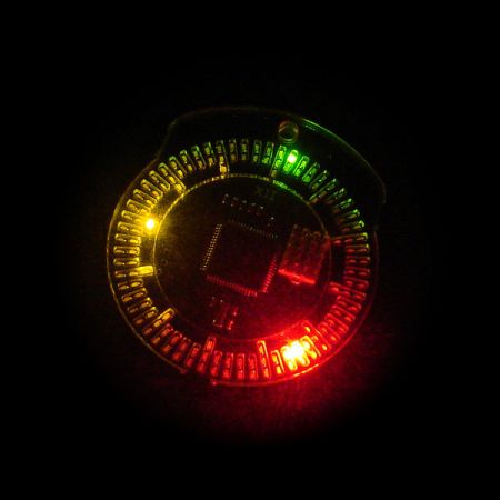
[Frank] wanted a classy way of telling the time, so he built up a LED Pocket Watch. The watch features 132 LEDs for displaying the time, two buttons to activate and change modes, a vibration motor, and a buzzer.
It’s controlled by a picoPower ATmega645P, which has enough pins to drive the array of LEDs, an internal real time clock, and low power consumption. The device is housed behind laser cut acrylic face, and sits in a 3D printed case.
To power the device, [Frank] used a rechargeable lithium coin cell battery. The charging circuitry is based on a MCP73831, which is an easy to integrate charge control IC. A USB connector is used to provide power to the board.
One of the bigger challenges of the design is driving the large array of LEDs. [Frank] uses Charlieplexing to group the LEDs and reduce the number of pins required. Another trick he used was offsetting the ISP header pins. This allows for programming the AVR without soldering a connector to the board.
[Frank]’s Instructables write-up is very detailed, and includes explanations of the schematic, PCB layout, software design, and case design. It’s a good read that details his design decisions.
After the break, watch [Frank]’s video overview of the project.


I had an idea for a similar project but as a larger handheld clock, was going to be for my 3yr old grand son to help teach him time (he just gets a kick out of led’s!).
it would only need 60 RGB LEDS. The idea would be the minutes would tick off in a continuous green circle, the hours would tick red for current hour( just the single led, not continuous) and the same for seconds except it would tick yellow(or blue).
THE TIME IS. BEEP. GREEN RED O’CLOCK AND YELLOW SECONDS. BEEP.
I few years ago I remember seeing either here or an sparkfun one of these that someone put in an actual old pocket watch casing. I couldn’t quickly find the original story, but here’s the link:
http://www.eng.yale.edu/pep5/pocket_watch.html
http://hackaday.com/2009/10/14/led-pocket-watch/
This does look a lot like paul pound’s pocket watch that Brian mentioned (minus the antique case and such)
I don’t get the need for this controller and pin count. Take a attiny43u and push the output through a chain of serial to parallel. Use the on-board boost to power the s2p devices, when the controller sleeps shut down the boost.
a daisy chain of CC controllers is definitely an option, it’s more about looks, I preferred the look of “one square chip dead center”
Fair point. I was purely looking at it from the energy budget side.
Would be cool if it could charge using one of those kinetic watch things. Or a small wheel on the side that connects to something like this:
http://www.digikey.com/product-detail/en/KHN4NX1RC/P14793CT-ND/2686253?cur=USD
I wonder if you could “wind it up” this way.
That’s the exact motor I already use in this pocket watch for vibration, I don’t think it spins well when you shake it, I didn’t see one that was “flat” when searching for stuff digikey had in stock, which might work better for what you are suggesting
Oh no, the shaking and the vibrator are 2 seperate suggestions.
In an old-school watch there’s a small wheel on the side to wind it. What if you had the same, but connected to a vibrator motor. If it’s a classic magnetic motor it should be possible to charge the device by winding it like with a mechanical watch. But I don’t know how much energy would come out.
was @ Frank Zhao, on mobile.
Pretty nice even though it has been done before. My only concern is that he is using the internal oscillator of the chip. In my experience internal oscillators are always off and a crystal or a resonator would definitely improve things. Especially since this is a clock.
The internal oscillator is only for the CPU, the actual time keeping timer is on a crystal
Ah, I’m so pleased someone has followed up on my first attempt. I redesigned mine but my academic career has kept me from releasing it. Good work Frank!
While I’m on the topic, this has also been a lesson for me about being open with your work. I always had the conceit that maybe I could commericalise what I’d done and turn it into a money-spinner, but realistically, that was never going to happen. I’ve had a lot of request for my source files over the years, but I was always coy. Now that this is openly available, I have to ask myself why I was ever reluctant. Any work I’ve done can be replicated by someone else.
That’s the moral for me: be free with your work and don’t imagine commercialisation unless you’re serious about it.
It sounds like you have a sweet job already, I doubt you would rather deal with mass production in China instead of those sweet helicopters.
Why not finally open yours too?
I have to say, I’m in agreement with Zee… there are some very key differences between your design and Frank’s, namely putting it into a classic antique watch case and making it work with the crown knob. I would LOVE to learn how you did that, because nice as this one is, I’m an absolute sucker for antique pocket watches. :)
And the difference between this and the hundreds of $2 Chinese ones on Ebay is……?I marvel at all the stuff on this site for yrs and lack Eknowledge,so forgive me.Does this trap mice also?
Do you have a link to something similar?
This’d be amazing on one of those glass substrate PCBs that’s been used on a few projects.
Looks like birth control disc.