DIY SMD Stencils Made With A Craft Cutter

Unless you’d like to spend hours with a toothpick and a tub of solder paste, stencils are the way to go whenever you’re placing SMD parts. While most commercial and industrial SMD stencils are made out of laser cut stainless steel, [Peter] figured out a piece of plastic and a $300 craft cutter is equally well suited for the job.

[Peter] has spent some time making SMD stencils out of polyester film in the form of overhead transparency sheets. This turned out to be a wonderful material; it’s dimensionally stable, commonly available, and just the right thickness suggested for SMD stencils. The polyester film was cut on a Silhouette Cameo, basically a desktop-sized vinyl cutter aimed at the craft market.

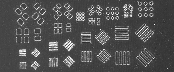
Stock, the Silhouette Cameo rounds off corners, not something [Peter] wanted with features only fractions of a millimeter. He came up with a tool to convert the paste layer of a Gerber file into separately drawn line segments, allowing him to cut SMD stencils for 0.3 mm pitch components.

It’s a great piece of work to make very fine pitch stencils, but we’re wondering if this tool could be used on the much less expensive Cricut paper and vinyl cutter that is unfortunately locked down with some very restrictive software.

Overclocking Microcontrollers

We’re all familiar with overclocking desktop computers; a wonderful introduction to thermal design power and the necessities of a good CPU cooler. [Marcelo] wanted to see how far he could overclock a microcontroller – in this case an ATMega328 – and ended up with a microcontroller designed for 20 MHz running at 30 MHz.

To verify that his uC could run at higher clock speeds, [Marcelo] began his experiments by uploading a piece of code that toggled a few pins as fast as possible. He needed to upload this code with a common 16 MHz crystal – AVRDude simply won’t work when a chip is clocked at higher speeds.

After successfully demonstrating his microcontroller will turn pins on and off at 30 MHz, [Marcelo] wanted to see if he could do something useful. By editing a single setting in his Arduino boards.txt file., [Marcelo] was able to have his overclocked microcontroller read and reply to characters sent over a serial connection. It worked, demonstrating an overclocked microcontroller could be useful in some situations.

As for what [Marcelo] plans to do with his faster microcontroller, he’s thinking of improving a ATMega-powered VGA color generator. A higher clock speed means he can push more pixels out to a VGA monitor.

Making A TARDIS Bigger On The Inside

tardis-pan

Over Thanksgiving, [Greg] had a little time on his hands and decided he needed an afternoon project. Having a few bits of plywood, an xacto knife, and some blue paint on hand meant a miniature TARDIS would take shape on his workbench. After finishing the model, [Greg] continued improving it with a blinky LED when the thought of adding an interior to the TARDIS entered his mind. An idea too good to pass up, really.

The TARDIS, of course, is smaller on the outside, so [Greg] needed a way to virtually model the interior of [9] and [10]’s home. After playing around with Blender for a few days, [Greg] had a reasonable 3D facsimile of the TARDIS interior. Now the only problem was to display it behind the front door.

[Greg] whipped up a small app for his phone that reads a zebra print pattern behind the door and overlays the 3D modeled TARDIS interior. Yes, it’s only viewable through augmented reality, but tilting the desktop TARDIS from side to side makes the entire console room visible. You can check out [Greg]’s TARDIS interior in the video after the break.

Continue reading “Making A TARDIS Bigger On The Inside”