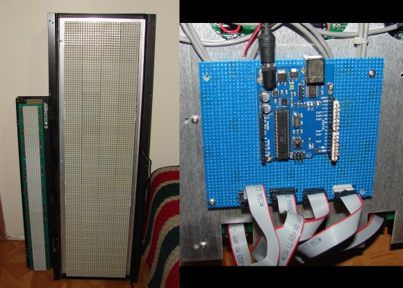
The LED signs sitting idle on the left are brought to life by an Arduino replacement driver shown to the right. The big one is made by Signature Electronic and used as an advertising display like you would see in front of a business. [Bob Davis] picked it up on eBay being sold as non-working. After some power supply repair he set to the task of driving them with his own hardware.
The images he shared give us a good look at the parts used on the sign. The display area is made up of a set of eight 8×5 pixel LED modules. Each module has a key and slot in the top and bottom to help align the rows properly when building a larger array. They use TPIC6B595 shift registers (the same ones seen in yesterday’s low-res gaming hack) and 74HCT138 decoders to multiplex the pixels. Most of this info is shared in the second part of his post.
He hasn’t quite gotten the larger sign to run properly. Each row displays the same data but one pixel lower than the last. If you’ve got some insight on why this is happening we’re sure he’d like to hear about it.
[via Dangerous Prototypes]


NEI I’m just armchairing this but….
If his panels are blinking as he activates more panels, then he probably needs to learn to access the AVR I/O directly instead of depending on the Arduino environment to do it for him. IIRC there’s a lot of under the hood stuff the Arduino platform does with I/O that hurts performance.
If his displays are repeating then the obvious place to check would be his I/O. Based on his writing and the anemic schematic he’s probably not interfacing with his 138 correctly. He’s sharing the same IO between all of his 138s so naturally, they’re all going to display the same data.
Oops, that was a ruined chain of thought. The 138 should be acting as his column or row select and the 595 is the shifted data. Anyways, the point still stands. He’s either not paying attention (like I was just now) to the hardware or his software is crap. Hard to say without looking at the actual hardware.
Step 1 upgrade to a bigger faster Arduino. That big sign is going to need a lot of processing speed to display cleanly and handle the Arduino overhead.
Step2, Shifted down means there is a bit there he is missing in the data stream, possibly addressing is required for each row and the only reason they are showing is because of overflow. Are each row simply a long shift register? more closeup photos and possibly hand drawn schematics of the row logic is needed.
I just noticed that the HaD post mentions one pixel but the original page states “one position”. I took that to mean “one character position”. Which is it? If it’s one char posiition, then the bug looks like it lies with him writing the same data to two shift registers. Without even a hand drawn schematic, it’s a waste of our time.
Nice matrix.
But, Bob, you were wrong on this one: http://www.bobdavis321.blogspot.de/2012/10/hurricane-sandy.html
Wow, is he [Bob] tolling?
That looks very similar to this sign, where I built a replacement controller.
http://llama.freegeek.org/~pjs/ledsign.html
That looks very similar to this sign, where I built a replacement controller from 2 AVR chips.
http://llama.freegeek.org/~pjs/ledsign.html
I bought the same sign from ebay. I had been concentrating on getting the original controller to work – It’s an RS-485 interface. I can send data in, but without knowing the protocol, nothing shows up. I tried sending all the known led sign protocols down the wire (and variants thereof) with no dice.
I was able to dump the roms and merge them (split odd/even addressing… always fun). Nothing obvious in the text strings, and I figured it would be easier to roll my own controller than to reverse engineer their machine code.
Put the project aside for a couple of weeks and this pops up. – Nice :)
Hopefully I can help figure out the last few steps of driving the matrix.
Maybe you could help me with my software?
I have greatly improved the code. The sign now works for all 4 rows from an Arduino. However it does still flicker. I am now manually codeing the serial out, that way I can send 8 serial data streams (Red and Green for 4 rows) to the sign with one clock pulse.
This may be a buffering issue, indexing/addressing issue, or just a weird combination of both. He might want to check to see if the data he’s sending needs to be null terminating or that the index needs to be inc/dec.
I did the same using the SPI peripheral of a STM32F0 development board for a 24×6 5×7 matrix board. IO using the arduino libraries is SSSLLLLOOOOOWWWW.
The roms and merge them (split odd/even addressing… always fun). Nothing obvious in the text strings, a
he’s sending needs to be null terminating or that the index needs
never
????????????????????????