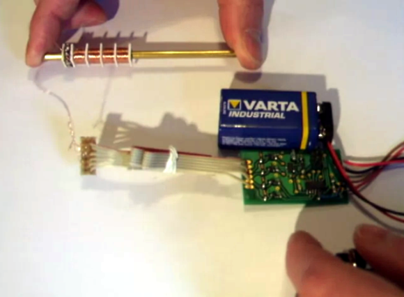
We admit that this project doesn’t have very many details available, but it was just too neat for us to pass up. It’s a small linear motor which [ligonapProduktion] built after seeing a very brief description of a commercially available version.
The video after the break shows him testing the motor. In this screenshot he’s holding the center shaft while the coil assembly moves back and forth. But it works with a stationary coil moving the rod as well. The motor is basically a modified solenoid. There are sixteen neodymium magnets inside the shaft. The set of four coils is driven by an ATtiny44. Just like a stepper motor, energizing the coils in the correct order pushes against the rare earth magnets creating motion.
We’re not sure if he has any use in mind for this build. For us we just like to see the concept in practice (we feel the same way about a homopolar motor build).
[via Reddit]


Hmm, seems like basically a controlled coil gun?
http://www.youtube.com/watch?v=mdZo_keUoEs
The regular actuators are bistable or made monostable by building in a spring. What this person did was introduce stepped linear movement, I can’t remember ever seeing that feature in this form.
I think there are people/developers waiting for this kind of setup. E.g. (miniature) robotics often uses linear controlled motion but they use (stepper) motors and transform that rotation to linear motion – which makes the design clunky.
I think the killer app for a small, light weight, linear servo like this would be RC models and UAVs. Most RC servos just use the servo arm to create linear motion in the first place. This short circuits that hack.
Just want to know what kinds of neodymium magnets you used ?
That would be neat for the MIDI xylophone I want to build
I think you’d be better off with a actuator above each bar instead of moving the mallets or the whole board.
Looks nice! Seems like a neat thing to just have on my desk at work, too, hehe.
I can see where this device could be used for a rotoswith with several different operation and it could also be programed to swith many functions.
Possible use to the 3D printing community?
I actually use one of these in my day job! The real, industrial version. They are quite strong and accurate, and there is a significant air gap between the drive bar and the coil housing, so it’s good for dirty environments.
They also don’t require any lube like a rack and pinion or ball screw, so they are good for clean environments too!
any one can provide more details ..
how to make the shaft? the coil? the control software and circuit ?
very interesting for DIY !!
I’d think the rod is actually a tube holding the magnets. Controlling could be identical to unipolar or bipolar stepper motors (I’d guess this is unipolar, since it’s using 4 coils). I think most industrial versions are actually 3-fase systems, and are controlled like 3-phase permanent magnet motors (with block or sine wave commutation), and with or without hall sensors.
The video clearly shows the difficulties you get when most friction and thus mechanical dampening is lost; it becomes a mass and spring system which is insanely difficult to stabilise with closed loop systems.
actually i only see 2 connections being made at the pcb end not 3 or 4 so this tells us that this for coils are lined up in series so you’re left with the very top wire bring it down to meet with the bottom wire and this two is what gets connected to the pcb.
tho we do notice a bigger pcb with 6 connections so even doing the math 2×4=8 tho we only see 6 connections so im not sure whats going on here but each coil should have one+ and one- and there’s 4 total so that should be 8 wires for each setup but we see 6ports on the pcb so im lost
I wonder if you could make the motion smoother by powering the coils with pwm and gradually transitioning from one fully engaged coil to the next.
smoothness would be the thickness of the magnets.. thinner magnets means the coils can align to a tighter width.. though this then means that the coils have to be thinner.. though the flip side of this is sorta microstepping the motor and driving two coils like you say.. there must be a most efficient method.. *cue experiments*
i thought about this and asked the guy who made this video but no reply yet
Think about a giant “mobile” version lifting almost everything up for example a light pole, the necessary current might be mind blowing, not shure if harmonics will interfere with other devices (if you just use the amplified GPIO outputs of an uC)
If the coils are 6mm and the magnets are 6mm, then presumably at some point they are perfectly aligned – and perhaps this is causing the stuttering (or effectively cogging) in the system?
If the magnets were 6mm and the coils were 7.5 mm then energizing each coil sequentially would result in a resolution of 1.5mm. And that’s before any microstepping.
where does this formula comes from ? or how can one be used for a prototyping phase?
If the shaft was one big long magnet. It would move even with a single coil continuously turned on , right?
i was wondering the same but ppl give up quick and stop sharing info