When you need a toroid the easiest source is often to wind it yourself. The problem being that placing a few hundred windings around a ferrite ring is a real drag, especially if you have to make several of them. This cheat developed by [Jim W.] will save a lot of time. He cuts the ring in half for the winding and reassembles it afterward.
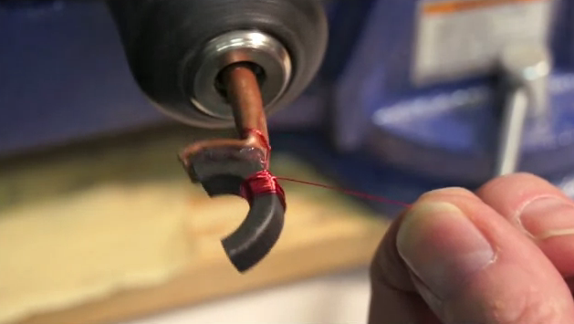
Here you can see that he has half of the core mounted in a drill chuck. To get to this point he scored the ferrite before clamping half in a vice and whacking the extruding half with a block of wood and a hammer. He hasn’t found a perfect solution for scoring the material (a utility knife or a triangular file both work but have drawbacks). Leave a comment if you’ve got any bright ideas.
Once the core is in two pieces he used some copper pipe with one end flattened and bent to the shape of the ring segment. With it hot glued in place he takes it for a spin (shown in the clip after the break). Once the windings are done a bit of super glue recombines the halves. This sort of thing is great for monitoring power use.
[Thanks Ted via Workshop88 blog]


Seems like a neat idea, but would this affect the magnetic field/properties of it etc?
Not much.
AC tends to generate resistive losses through hysteresis and eddy currents. These are minimized by making the magnetic bits smaller. The Toroid material is actually a mixture of tiny grains of magnetic material in a plastic binder, so there’s no continuous loop of magnetic material. Breaking and reassembling a toroid will have minimal effect.
Some cable EMI suppression systems use 2-piece “C”-style clamp-on units that take advantage of this.
You’re mixing up low permeability iron dust cores with high permeability ferrites.
You can glue together a cracked iron dust core with nearly no change in AL, ferrite… not so much.
Why’s that? Ferrite is just glued-together iron particles right? Is the particle size important? Some treatment of the iron? The glue?
Please read: http://en.wikipedia.org/wiki/Magnetic_core
There is info about ferrites, iron powder and EI cores.
Right. Please tell me you don’t work with anything electronic. But yeah, in measurement applications where the fact you can take it apart is very advantageous in extreme cicrumstances you could do this.
Whole point of toroids is to have higher quality transformers/inductors. If you don’t wanna wind them just get some freaking EI metal and get uncomparable quality to this.
Looks up “El Metal”. Gets page on “metal” in Spanish Wikipedia. Doh!
it’s E I not E L
Well sorry for not having read the dictionary of magnetism, jc. Jackass.
We can thank the people who gave us fonts
that display an “I” or an “L” and often a “1”
as an identical appearing screen character.
…has made serial numbers and passwords
quite a bit of non-fun over the years.
I wasn’t replying to you, I was replying to Barrabas. It’s totally ok not to know but it’s not ok to PRETEND you know.
As mentioned below, experimentally the inductance drops by 30%. That counts as “not much”, although I probably could have been more specific.
I’ve done this same trick and was able to get roughly 10% loss in inductance by being careful. That’s definitely in the “not much” category; but again, I could have been more specific.
Thanks for keeping us honest, jc.
That is not correct breaking the core and doing this is a very bad idea
glass cutting wheel for the scoring.
wouldn’t the glass break?
after so much time on the internets I think i’ve become jaded. i have no idea if you’re attempting humour there or just plain stupid?
Your comment reads as if it says a cutting wheel made of glass as opposed to a cutting wheel that cuts glass.
Everyone is mentioning the effect that breaking the toroid would have but there’s also the possible effect of getting it near a permanant magnet! Depending on the material it could raide the inductance and destroy the high-frequency Q. Not many manufacturers make this type of material anymore but it’s still around. You get it near a magnet and it will permanently change the magnetics.
The permeability of super glue used to join the two ends of toroid will affect the magnetic properties. But, That wont be much unless “scientific precision” is required…
Great Job!
I’ve done this several times – the problem is it reduces the inductance by a factor of TEN. There is no way to get that core back together tightly enough.
It’s not that difficult to just buy a current transformer, if that is the actual intended goal (power monitoring). I’ve bought a few over the years and they are relatively common, imho.
The expensive current probes from Tek and the like use a split ferrite core with one piece on a sliding arm for inserting the wire to test. Once closed there’s nothing but the mechanism forcing the two pieces together. I’d imagine that after being superglued and clamped this is just as effective.
Given he’s not lapping the surfaces or clamping them (that locking mechanism on the good probes clamps the lapped surfaces together) he’s not getting anywhere near a good mate between the two core halves.
If cracked apart the halves should go back together perfectly despite not being “flat”. BMW use the same approach for the big end of conrods. Take a metal part, snap it in half put a thing through the hole and join it back together again. They reckon they get better accuracy that way and I can believe it. I would be tempted to use some sort of nut/bolt mechanism to hold the core firmly together rather than just glue, but superglue if used in suitably thin layer should make a very close join.
That assumes perfectly brittle fracture… any material that necks before failure like a mild steel would not go back together at all. Any material that suffers additional fracturing would also not fit together, once you clean the dust off your surfaces air gaps will be introduced.
that’s true, i’ve seen the exact same thing on a golf GTI mk 5. you should try cutting the ferromagnetic rings just like they cut piston rings. think of a sort of guillotine, a strong blade pressing sideways against your ring.
Actually, cracking caps is done to reduce cost, and for no other reason. The same is true of powdered metal rods, which are both more likely to fail and more likely to behave catastrophically in a failure situation than good old forged metal rods. If anyone tells you that they get better results by sintering metal and then cracking caps, they are lying to you and they are lying hard. The best results are gotten by forging and machining.
sintered parts almost certainly have huge numbers of micro cracks uniformly distributed throughout the material- working as stress initiators/concentrators throughout the material -hence the likelyhood of catastrophic failures. Weight for weight, sintered materials could perhaps be better than “solid” but only if the powder started out with particles smaller than the grain size of “solid” metal . Forging/machining also likely to work harden the surface which is where most cracks start.
Can sintered parts be case hardened successfully?
where did you put that damn tweet button? I gotta tweet this.
Maybe try measuring the inductance of a dozen of turns or so on the core before and after the “cheat”.
For something with high permeability like ferrite, your air(superglue)-gap will lower your effective inductance by an order of magnitude.
Just do what everyone else does, wind your magnet wire lengthwise on a small stick and thread it.
200 turns is a <10 minute job that way and you don't have to destroy half a dozen cores to get one questionably "good" one.
Another way to wind lots of turns on a toroid is what I call a “punk method”. Take ten parallel lengths of wire, optionally lightly twisted together. Wind the coil with one tenth of the turns. Then connect the “sub-coils” to series (while checking with a meter that you aren’t connecting them into loops instead). The connections lining the coil then look like a punk mohawk hairstyle (hence the method name).
Selection of the approach then depends on the number of turns, balancing the work saved with winding against additional work by connecting the segments.
An added advantage for experiments is that the segmented windings can be used at will for ad-hoc forming of transformers or tapped coils.
Wow. I think this adds another underground floor for the bar of electromagnetism understanding here on HAD.
I don’t understand your comment, do you mean not enough people on here understand electromagnetism?
i think you can get split ferrite beads.
inside of some tv/monitors they are used on the bundle of wires from the vga cable right at the board.
they are indicated with a plastic clamp around them with 2 lock buckles that can be lifted with fingernail or razor blade and split apart.
you can do anything, from a em theory standpoint this reduces the quality of the core. air is a low permitivity material, ferrite is a high permitivity material. there is a formula to model the damage done by cutting the ferrite, for most applications you can get away with the cut, for some you can’t. this is a method that will allow you to speed up your work when you can get away with a cut.
another method for scoring, hmmm, let’s think…. ever hear of a dremel tool?!
FWIW (and even with assorted tools,tricks & tips) I have never managed to cleanly break such torroids…
the core is big enough, wind the wire on a bobbin (ie shuttle)…
for higher perm cores (with permeability above 100 ish) this will lower the magnetizing inductance alot. some times that is a good thing as it reduces the MMF across the ferrite and shits it to the air gap. Usually air gaps in ferrite are done with a diamond saw. Ceramic magnetics sells them.
Tsk, tsk, tsk. Such language! About E and M of all things!
Unpleasant imagery… Can’t get it out of my head now.
blushing, the lack of a “f” changes everything… ;-)
I suppose that if you are just using it for a current transformer at 60Hz you could care less about the permeability of the core (so long as it is still significantly greater than air…), however a much easier solution for a situation like this is to just cascade 2 current transformers, see something like http://www.easternvoltageresearch.com/flexibrute_currentxfmrs.html
When you cut the toroid apart and glue it back together you change its magnetic characteristics. Because you can’t perfectly reassemble the toroid, the gap left in both cuts reduces the magnetic flux density, reduces the coil’s inductance and causes spurious magnetic fields around the cuts.
Put it on a network analyzer please.
Having worked in the magnetics industry, I can guarantee you that I can wind 200 turns of wire on a toroid faster than going through all those steps, especially if the lay is not important. The trick is to make a spring with the magnet wire, roughly half of the diameter of the inside diameter of the coil you want to wind. This allows you to keep the length you are pulling through each time, reasonable. As you wind, you unwind enough of the spring to be convenient. A panavise or similar articulated vise is great for holding the core as you wind the other half, turning it to wind the other portion. A crocheting needle or plastic rod whittled into a hook, makes a great tool for pulling the wire through. Hope this helps someone.
I’ve kept a small crochet hook/needle in my prime toolbox for over 30 years. I got a lot of laughs from my classmates in Electronics Lab… until one day a spring in an 8-track player came off inside the mechanism, and they couldn’t think of a way to re-hook it.
…
Later, they asked, “Where can I get one of those?” B^)
No toolbox should be without what I call a “paperclip tool,” something my sons have taken to also. I just straighten out a paperclip, and, using needlenose pliers, put a hook in one end and a reverse hook (for pushing) in the other.
+1 !
Toroid do not work that way… 1st year physics will explain why.
It won’t work……. if it did then they would not spend a fortune manufacturing a machine that could wind a Toroidal. ESP. as the production speed is severely impacted by having to wind the coil into a sealed ring.(yep it seams like magic, but you can indeed wind into a sealed ring…….)
So the question arises why they don’t do it this way.
But to make the understanding simple… take a bar magnet and snap it in half.. Then try to put the two parts together again.
Seeing that both halves would be still magnetized in the same direction, they’d just stick back together. South to north.
i believe he meant snap it back together and then observe how strong the magnetic field from it is. significantly less than the unbroken state.
You have never tried breaking a magnet i see. The split will repel not attract itself.
depends on which axis you break it on.
aaaand we’re getting closer :)
http://www.youtube.com/watch?v=E-FpeRf3RvQ
There are also pot cores and E cores (see http://www.fair-rite.com/cgibin/catalog.pgm#select:freq1 for both) which come in halves and you wind the coil(s) onto a bobbin before putting the halves together onto the bobbin. Amidon Associates (https://www.amidoncorp.com/) is good for hobbyists who want to buy very small quantities of cores at a time, but their website just says “image coming soon” for everything. 25+ years ago I used to buy different kinds of cores from them frequently for both RF and audio applications.
OK guys, thanks for keeping me honest. I wound 30 turns on a toroid core, made some measurements, broke and superglued it, and made some more measurements. Using a voltage divider with a carbon resistor driven at 1 KHz, the inductance was reduced by about 30%. Finding the resonant frequency of the coil in a parallel tank (a less precise measurement, and adding the variable of frequency response of the core material), the inductance dropped by about 45%. Not an order of magnitude, but significant.
Thanks for the tips on winding techniques, too!
More details here: http://jimlaurwilliams.org/wordpress/?p=3337.
Wow, 30% inductors… 20% resistors, 20% caps… how does all this fasinating electronics stuff ever work….? The snobbery over electromagnetism is almost astounding as the grammar nazis. Leave yourself some extra wire and add a couple of more winds to adjust to taste. This is a HOBBY site and those crappy circuitboards you are farming out to china to make for you are going to have more of an effect on your circuit than a crack in your inductor core is ever going to have at frequencies you are ever going to be able to work at reasonably when widing your own inductors or fabbing your own boards. “But my EM professor says….” PSHHHHHH!!!! a metric ton of theory won’t buy you a gram of reality…
This technique can work but you have to be VERY VERY careful that the ends join properly at the end and are completely flat, and even so you wind up with a slight gap and greater core losses than you started out with.
One of the classic ways do deal with this problem and at least cut your losses to a minimum came out of the early Skylab research:
http://ntrs.nasa.gov/search.jsp?R=19730000391&hterms=fixture+winding+transformers&qs=Ntx%3Dmode%2520matchallpartial%2520%26Ntk%3DAll%26N%3D0%26Ntt%3Dfixture%2520for%2520winding%2520transformers
One other effect that was not mentioned yet and may not be important in the specific use-case is the micro-structure of the ferrite ceramic. Any vibration or shock above a certain G threshold will change the micro-structure of the core lowering its Al and potential Q factors (example below). Also winding ring-cores is a chore but I’m of the opinion, less of a chore than what was described above.
One of my previous careers was in wound component manufacture and we found this out to the consternation of a client (UK MOD) when we sub-contracted to a major military contractor to make the tuning coils for the new man-pack radios.
They specified the coil design and provided cores, pre tested by them. Only, after THEIR acceptance test of the core (originally packed on foam recessed sheets) they shipped them to us loose in a Ziplock bag. On receipt our CTO yanked them from the production floor and asked me to do a Q-probe tuning test. Only 12% of the cores met the same spec. We contacted the main contractor and suggested they ship again but let us do the acceptance testing, their reply was that they could not do that as their quality management rules required testing before shipping to a sub-contractor.
Cutting the core works well for powdered iron mixes, but with ferrite compositions, you must ensure the cutting operation does not heat the core beyond the Curie temperature of the ferrite. That can greatly affect the permeability and the uniformity of permeability near the cut.
I wouldn’t do this if you’re using the toroid to make a transformer for an SMPS. You generally want the winding spaced evenly around the toroid. This method is going to have very high flux densities where the winding is. It’ll probably saturate the core there. But if it’s used to make a current transformer, I think it’ll be OK. Though I’d imagine laminated steel would be better for a CT at 60Hz…ferrite is usually for higher frequency stuff.
winding around flexible plastic tube. press ferrite power hard into tube. Then bend tube, and glue ends to form a toroid.
About seperating the toroid to get two halves… Why not use a dremel tool with mini cutting blade? That will have minimal effect, and not so much ruin the material.
https://www.youtube.com/watch?v=zL51M-0ebXc
Sorry but this is a bad idea, once you break/cut what ever you want to call it …you will have tremendous loss… you can always contact us to wind toroids we do it every day in our NY factory and have been since 1956.
Another material is kool mu is sensible cost and it has demonstrate the Magnet Wire lower adversities and essentially incredible warm properties when related with controlled iron focuses.
throughout this system the shaft on that reel is mounted is turned manually with paddle assembly. the patron can management at intervals speed. The circle winding machine is given reel, spool and it might be applying specific endeavors.automatic winding machine