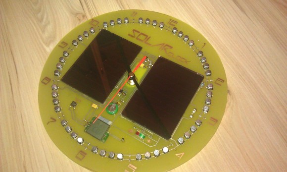
This solar clock was built using a lot of salvaged parts. We find it interesting that [Nereus] combined a ring of storage capacitors with a power cell (translated) to create a hybrid energy storage setup.
The machine translation makes it a bit rough to understand how this works, but the schematic helps quite a bit. The pair of solar cells, which were pulled from some cheap solar cellphone chargers, feed the bank of capacitors encircling the clock face. If placed in a room that gets plenty of sunlight the cells will top off the capacitors which then feed an ICL7663 regulator. We’d love to hear comments on this part choice, as it’s our experience that linear regulators are rather inefficient. But anyway, the regulated power feeds both the energy cell as well as the clock motor. When output from the regulator dips the battery picks up the slack. The project also includes a voltometer and thermometer which can be displayed on the tiny LCD screen just about the six o’clock tick mark.
Now if you want something completely battery-free you’ll have to check out [Jack Buffington’s] take on solar clock.
[Thanks Manekinen]


Awesome! Talk about daylight saving time, uh! UH!
I know, I suck, but somebody had to say it.
Sure a linear regulator is inefficient, but when you’re talking about such a small power draw that a AA battery lasts at least a month i don’t think it’s anything to worry about. Also the voltage drop isn’t much. The other thing to consider is the power draw of a switching regulator’s control circuit, in a situation like this could easily waste more energy than the linear regulator.
The efficiency of a switching mode regulator scales with the load. A linear regulator’s efficiency will depend only on the difference in voltage between source and load, so it’s about as efficient at 1 amp and 1 microamp. For very small amounts of power, a charge pump could be a better option, but it won’t be easy to find.
I disagree, a switching circuit has more fixed losses than a simple transistor linear regulator. If we’re talking milliamps or higher then sure the switching circuit is a no-brainer. But as the load approaches zero this will become a large % of the total loss.
A linear regulator will bleed current because it has to establish an internal voltage reference. See: http://www.ti.com/lit/ds/symlink/lm317l.pdf
It passes between 50-100 μA to keep that voltage reference depending on the difference in voltage.
Oh, A voltometer!
Linear regulators are inefficient – but only in relation to the amount of current they are regulating. In an application like this you want to select a regulator based on quiescent current, which is how much current is being consumed by the regulator when there is no load. If a regulator has a very low quiescent current rating, then it will draw very little power when little or no current is being used by the load. The regulator they chose uses only 10 uA when there is no load present.
This is a really neat project. Well done!
So HaD picks up an inefficient regulator choice on a really nicely executed project, but happily posts other stuff which is dangerous and/or pants-on-head retarded without so much as passing comment?
So?
I once heard about these other pants-on-head, even dangerous projects like “sending a man to the moon”, the “horseless carriage”, “skyscrapers”, and “the internet”.
It all starts with an idea, no matter how mundane. ;P
If the idea is “How about using an unsuitable material to do something dangerous, just because it’s cheap and readily available.”, where do you think it can go?
It’s like promoting the old Jolly Roger book that’s been circling the net for ages, full of misconceptions, dangerous receipes and irresponsible stunts written by 13 year olds in the 70’s. Not a good idea.
This is very cool. Wouldn’t mind buying one of these :)
An alternative to the design would be to use tantalum capacitor (or multiple ceramic) from 2 different manufacturers (say, orange and black) and use them in the place of the electrolytic ones.
Then you could see the most significant parts of the needle path more clearly.
Note that solar panels should be in direct sunlight and not be partly shaded
So making a clock this way isnt good, the point is that if part of solar cells dont recieve sunlight but are shaded (however tiny factor this is) those parts become resistors, and degrede performance a lot so putting arrows over the cells …well maybe not that good, although its a nice design.
They look like amorphous panels which are specifically sold as being shade tolerant, compared to mono/poly panels which don’t do so well with shade.