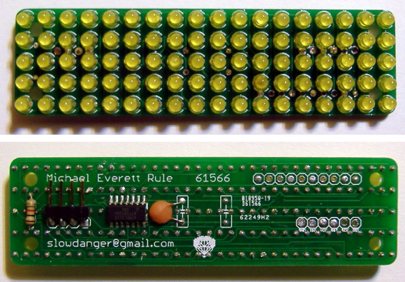
[Michael] built his own LED marquee using individual diodes. Despite his choice to forego the 8×8 or 5×7 modules we often see in these projects, his decision to spin a dedicated PCB saved him a lot of trouble during assembly. Sure, he still had to solder 180 leads on the 9×18 grid of lights, but at least he didn’t have to deal with wiring up the complex display layout.
The chip driving the display is an ATtiny24. You can see that it’s an SMD package and spans one row of the through hole LED footprint. There are way too few pins to drive a multiplexed display of this size. Instead of adding a separate driver IC he decided to design the display to use Charlieplexing. We didn’t see a schematic for the project, but judging from the board images all of the I/O pins are used by either the display itself, or the serial connection provided by that right angle pin header.


You know, maybe it’s just me, but that looks a lot more like a 5×18 grid of LEDs, not a 9×18 grid of LEDs. Maybe numbers have different meanings to HAD editors than the rest of us?
Geeez Yarr, well done, first post and a snipe too, bet your mum is proud of you.
aannnnd even if it was 9×18, how is that 180 LEDs? Last time I checked that was 162.
5*18 = 90 LEDs, 2 leads each = 180 leads.
Summary clearly states 180 _leads_.. which is correct.
From the blog post; “The hardware consists of 90 3mm LEDs arranged in a 5×18 grid.” 5*18 most certainly is 90 LEDs… But I am still unclear how a matrix of 9×18 is 180 LEDs
Hate to tell you this: but you might need glasses since you can’t discern the difference between ‘leads’ and ‘LED’.
Or are you using an old smartphone with a small composite CRT display?
Also FYI tvheadedrobots = Skip. I wasn’t logged into WordPress for my first comment, sorry.
I like the compact nature of his design. Discrete hell yes. This would be a cool display for another project.
missed importunity for total DIP badassness with that one SMD driver there XP
and may i add having to solder many MANY kits together with lots of leads i started to find soldering zen XP
Those were the fumes I think
but mmm… where are the resistors? That ATtiny won’t last very long this way.. nor will the LEDs.
With the “right” supply voltage, color of LEDs and a low enough duty cycle (which you’re likely forced into through multiplexing), it can be made to be a don’t care. Many LEDs (at least IRs) can comfortably take 5-10x of their maximum steady-state current at low enough duty cycles. It’s not rocket-science — algebra and a datasheet.
That ATtiny can’t drive enough current to damage those LEDs, especially not since they are not on more than maybe 20% even with a fully lit display.
Also the internal resistance of the AVR ports is high enough that if you are just careful about supply there is no problem at all.
Wouldn’t do this with synthetic saphire LEDs though, (blue, high power green, UV, white) since they are much more sensitive to high currents.
Even if you are off by just 0.2V (and you basically can’t know, because of manufacturing tolerances), current will shoot through the roof (to like 80mA) and kill your AVR, especially considering the overall current limit for the AVR (not just the per-pin limit). This is just bad practice, even when PWM’ing the LEDs (which may save the LEDs, but likely not the AVR).
You’re safe as the variables are all known. Voltage is a given, current is known as there is only one LED on at a time, and the LED on-time is also known, being refreshes per second / LEDs (5 * 18).
So if you update the display once a second, the LED on time is 1/90 seconds, say 10 milliseconds. Refresh 10 time a second and you’re down to nearly 1 millisecond.
As @ewertz says you can take those numbers (say 5v for 1ms), work out the current and check the datasheet to see if the LED can handle it. It probably can.
Even if the LED may, the AVR can’t. And like I said, you almost by definition don’t have all the variables, as different LEDs have slightly different forward voltages. These small differences in forward voltage translate into huge differences in current. Too much for the AVR to handle (I believe it has a max. of 40mA per pin or so). See also http://electronics.stackexchange.com/questions/12865/is-a-current-limiting-resistor-required-for-leds-if-the-forward-voltage-and-supp
You need to check what the peak current rating is both for the AVR & LED.
The link you gave is for the LED being permanently on, in this case the LED is only on for a tiny fraction of a second. The peak LED current is time dependant – the shorter the time, the higher the current. It’s in the datasheet.
The maximum current for continuous duty (as per the link) may only be 20mA, but peak may be 500mA for a millisecond (seriously, look at IR LEDs for remote controls).
You may think this is a bad circuit, but Charlieplexing is very common, and multiplexing LEDs even more so. Both schemes rely on driving the LED well above their continuous current rating.
Once again, with a low enough supply voltage, you can even leave the (yellow) LED on 100% of the time and be within the specs for both the pin drive current and the LED.
Again, the the max. current per pin on the ATtiny24 is 40mA. You can’t go above that, even when using PWM. The docs for the ATtiny24 specifically mention that “Stresses beyond those listed under “Absolute Maximum Ratings” may cause permanent dam- age to the device.” Yes, charlieplexing and multiplexing an LED matrix is common, but that doesn’t mean you don’t need resistors. And the problem is that you don’t know the exact forward voltage of each LED (even if you, and being off by only a tiny amount causes a huge increase in current. That’s why you need current limiting resistors in the first place. It’s interesting how many people just completely ignore this and pretend it’s save to do this, when it’s not: it will damage the ATtiny, trust me (unless you’re running this from some current limiting power supply). See also: http://electronics.stackexchange.com/questions/28393/why-do-we-need-resistors-in-led
There is a pretty high internal resistance in the AVR output pins, the old LEDs also have a high internal resistance.
The forward current at a given voltage for yellow LEDs is usually VERY well defined. Old type yellow green (same process) LEDs were used as voltage references.
This guy has it right. The pin driving fets have such a high On resistance that you could direct drive leds without going over the pin’s current rating.
DS: Well, within reason. I wouldn’t direct drive an LED connected between VCC and a pin with 5V VCC and one of these ~2V LEDs, but with the LEDs connected between two outputs (which means two output resistances plus the internal resistance of the LED) should be able to work on 5V, probably. I would like to see this device powered off 3.3V or so though.
James,
Read the rest of the ATTiny datasheet. At VCC=3V, the best voltage you can get between two IO pins is 1.55V @ 20mA. At VCC=5V it is 3.95V @ 20mA. Extrapolating the graphs in the spec sheet for 40mA @Vcc=5V the voltage between two IO pins goes down to 2.9V.
Since Charlieplexing has such a low duty cycle, you want to overdrive the LEDs 2-3x times past their current ratting at a minimum. The internal resistance of the AVR will regulate the LEDs safely by dropping the voltage between the IO pins much like an external resistor would do.
I’m glad to see this discussion. I actually had the same reservations about burning the AtTiny but decided to try it anyway. It’s been running at my desk continuously for about a week now and I’ll be curious to see if it ever does die. The LEDs are fine, I checked the peak maximum current, and they draw less than this at the supply voltage, so resistors won’t be necessary. I actually took some liberties with the AtTiny which are outside of specification and I think may lead to.. “undefined” behavior. Specifically, instead of driving the LEDs one at a time, I actually drive them 9 at a time, as if I were multiplexing. The problem with this is then that one IO pin in the Tiny might need to sink up to 9 IO pins worth of current, passing through the LEDs. The consequence is that sometimes some LEDs are ever so imperceptably more dim than others — but I don’t mind this. The real question is what will happen to the AtTiny over time being asked to sink so much current. I suspect that it will be fine, and that the internal resistance of the AVR will be sufficient to limit the current to safe levels. But, we shall see.
I was considering doing exactly this for a project I’m currently working on, but decided against it. 16×16 LED’s plus shift registers on a perfboard would be a little much… custom PCB makes things much nicer.
Pah, amateurs. I’ve done one with 24×18 discrete LEDs on stripboard. Cutting the tracks and weaving wires through it for columns was a pig.
I’m most impressed with the many-LED 3D cubes, to get that to go nicely seems a bit of a pain from my perspective.