Most 3D printers use stepper motors to control the movement of the extruder head. If you could actually print those motors it would be one more big step toward self-replicating hardware. Now obviously [Chris Hawkins’] working 3d printed stepper motor wasn’t built 100% through 3D printing, but the majority of the parts were. All that he had to add was the electronic driver pieces, magnets, wire, and a few nails.
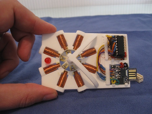
The coils are made up of nails wrapped in magnet wire. The rotor is a 3D printed framework which accepts neodymium rare earth magnets. The axle is pointed which reduces the friction where it meets the cone-shaped support on either side of the frame. The IC on the upper right is a transistor array that facilitates switching the 20V driving the coils. The board on the lower right is a Digispark, which is an ATtiny85 breakout board that includes a USB edge connector for programming and a linear regulator which is how he gets away with feeding 20V as the source.
Don’t miss the demo video after the break where you can see the motor stepping 7.5 degrees at a time.


Soon we will be able to contruct entirely a 3d printer with a 3d printer and some nails.
That’s Exactly the ideology behind the RepRap, which is a pretty old project now :)
That is pretty amazing. Obviously, you aren’t going to use this on a 3D printer, and he didn’t design it for that specifically, but it seems like with some proper bearings and some refinement, you could get those steps smaller…
Looking forward to seeing where this goes!
it feels the same as bitcoin mining on a NES, useless yet exciting!
I’m not so sure about calling this useless. I mean, yes it’s not ideal and it sure could be refined but it looks like it moves quite well (and fast). I’m sure that a useful application could be found for this.
Exactly. One of the things that bothers me with steppers is the connection to the axis/wheel/gear. In most cases I end up ordering extra bits. With this you could design the mechanical interface to fit your spare/salvaged parts.
Nice design and construction.
beautiful, nice use of a digispark, it’s like a stepper motor with all the electronics built into it, I like it!
Great Work! Next step… 3D print of the coil winders! Also, an adapter for a torque multiplier for over the top, and this might just be a replacement stepper for an extruder motor!
As far as the berrings go, nice work on taking in to account the greater angel for the mount than the spindle, I’ve had problems with ‘ snap tight ‘ model kits that didn’t do that kind of thing.
Bravo!
Very nice work. Can it be made strong enough for everyday use in a printer/bot with the current materials?
– Imagine could be ‘stacked’ for more torque?
Awsome!
Awsome
Interesting work, but how much work can the motor perform work? IMO the next step would be build a rotor with longer shaft, along with a shaft support that would allow the shaft to protrude. After that a simple prony brake could be made to measure the torque. I really don’t know if it would make any difference or not, but is the steel makeup of nails to inhibit them from being permanently magnetized over time? In any event probably a good beginning down this road in DIY 3D printer construction
Ideally one should use electrical (silicon) steel for the motor core; it should be laminated to reduce eddy currents; and shaped to fill the available space in order to get the strongest magnetic field for the wire being used. The nails may become magnetized, but not as strong as the electromagnetic effect so the motor will still work.
On a critical note. Motors are built around magnetic circuits. Using plastic for some parts is OK, but the rotor really should be magnetically conductive and there should be a magnetically conductive can (or at least a hoop) around the outside of the coils. If you don’t want to use steel in the rotor, a Halbach array is an efficient, if hard to assemble, alternative.
So a hoop of iron over, say, the middle of it, would do for whatever purposes? I wasn’t aware you needed to “ground” or “loop” or whatever with magnets. Learn something every day etc. Tho obviously motors work without it, so what would the benefits / losses be over using / not using one? Just interference?
For the motor itself, it bridges “proof of concept” / “prototype”. Nice start! I wouldn’t worry about buying in bearings, not sure anyone’s ever made plastic bearings worth a crap. Maybe nylon ones, in some cheap toys. But for the precision and wear and lifespan, it’s crazy to be pedantic about that. I’d buy in proper metal ones. Would even 2 steel balls do? Instead of a proper ball-race or whatever?
Also have to worry about the cost of including the MCU in it, but then one just as cheap could run several motors. If this was much cheaper than commercial steppers, that would be a gain. The increased bulk doesn’t matter so much. Maybe it would help in places where stepper motors are hard to get. The aim for 100% printable printers serves better as an ideal than a practical goal.
What else does this need apart from a few cogs to gear it down? And is 3D printing doomed to make brittle plasticky bits forever? Would this motor be strong enough?
There aren’t any magnetic monopoles, at least proper real ones, in existence. The point is that the magnetic field always loops back onto its source somehow. E.g. magnetic fields around a bar magnet are very much analogous to how electricity conducts through water when you drop an AA battery in it, and adding ferromagnetic material is like dropping in salt. There’s even analogs to Ohm’s and Kirchoff’s laws for magnetic circuits, and the better path you give for the field, the stronger the field strenght you get out of a magnet.
Which is of course why the clearances must be really small, because any air gap weakens the field, and why the entire rotor should be solid metal, and why you need a bell around the magnets etc. etc.
Which brings forth the question: how much iron filings could you mix in with the plastic before it becoms unprintable?
Now there is an idea. I’d like to see someone experiment with that concept. Would they present a rust risk in a humid environment?
I was thinking about that. Ferrite is a material with useful magnetic properties. It is also a type of ceramic. They already have 3d printers that work in ceramic- I wonder if you could 3d print unusual and useful shapes in ferrite. Also it doesn’t rust (I don’t think.)I was thinking about that. Ferrite is a material with useful magnetic properties. It is also a type of ceramic. They already have 3d printers that work in ceramic- I wonder if you could 3d print unusual and useful shapes in ferrite.I was thinking about that- ferrite is used in magnetic cores because of it’s magnet properties. It is a ceramic and they already 3d print certain ceramics. I wonder if you could 3d print weird and useful sh
Since there are already nails in the stator, I don’t see why there should be a problem putting nails in the rotor, to complete the magnetic circuit on that end. One nail straight through between two magnets, and four shorter pieces of nail to connect the other four magnets ought to do the trick, at least a good deal better than air.
The reason people get away with not completing magnetic circuits (up to a point), while electric circuits simply don’t work at all when you don’t complete them, is that air (or even vacuum) has considerably better permeability than conductivity. So to a certain extent, magnetic circuits are self-closing.
While 3D printers are cool, they are not the ultimate goal. They have a valid place in the construction process, but NOT at the expense of lathes, milling machines, CNCs or even coil-winders.
Take this motor, add some step-down gearing, and use that to build another, stronger motor. That I’d like to see!
I haven’t looked up the math, but does 8 coils give you a 7.5 deg. step?
Anyway, it’s impressive, nay, beautiful. I’ve got to try this sometime. If only I had a 3D printer…
There are 8 coils (45 degrees), but only 6 magnets (60 degrees). That gives a 15 degree difference, and the 7.5 degrees comes from half of that? I cant exactly explain it myself, but basically out of the six magnets, only one is lined up and energized at a time, the “next” one is offset by 7.5 degrees apparently. Im sure you could just draw it and do some easy trigonometry to prove that.
To get 7.5 degrees you would have to half step energizing two coils at a time
Wouldn’t you want to energize multiple coils for additional torque anyway?
Or is that seemingly sensible multiplier a rouge.
Oftentimes increasing the resolution is more important than torque unless of course you have a load so large that the lack of torque begins to affect the resolution. But I would say half stepping is still a pretty good balance between torque and resolution.
Since there are six poles on the rotor (30deg/pole) and eight on the stator (45deg/pole), this means that the nearest stable position each time you step it is 15 degrees away. I think he’s half-stepping it by energizing two coils at once to get the intermediate positions. This effectively gives the stator 16 poles. Now you’ve got 22.5deg pole spacing on the stator, so 30-22.5 = 7.5 degrees between stable rotor positions.
As some have already talked about in the comments, the 7.5 degrees comes from half-stepping. Instead of charging coil 1 then coil 2 etc, I charge coil 1, then coil 1 AND coil 2 (putting the rotor halfway between) then coil 2 etc. To be perfectly honest, this was the only way I could get it to work so I kinda HAD to do it that way. As some people have said, the 7.5 degrees comes from half-stepping.
Next step, PWM “wave” energizing of the coils to 1/4 step without losing torque.
Very cool. :)
Off the subject this could be an awesome start to a fully printed clock.
Awesome!
This is a great project, but I should mention that it’s not technically a stepper motor, it looks like a four-phase brushless DC motor. Stepper motors have teeth on the stator and rotor to allow it to achieve very fine angle control, allowing fractions of a degrees of travel per commutation.
This is really a DC brushless motor jumping between commutation steps. You can still achieve fine angle control, but you’d have to drive it with PWM, effectively using a sinusoidal drive but in stall mode.
Sounds like your arguing semantics.
The thing steps, therefore it is a stepper motor.
How the steps are generated is pretty much irrelevant.
Frankly, what you said is as ignorant as claiming a CNC machine with stepper motors is not a robot while a CNC machine with servo motors is. With the exception of the feedback loop of the servo motors, both systems operate pretty much the same.
Not arguing semantics, just a technicality. I’m not overly concerned about it so let’s not start a flame war. The term “stepper motor” is actually a classification term, referring specifically to the class of motor that has toothed rotor and stators. You’re suggesting that it be used as a descriptive term, to encompasses any motor that steps. However for the purpose of identifying motors, it’s not a useful description because almost all permanent magnet and switched reluctance motors need to commutate, and therefore could be considered to “step”.
Not all motors can be classified as a “stepper motor” even if they do happen to commutate in a discrete fashion. A classification name does not detract anything from the motor itself, it’s just a name that serves used to uniquely identify the type of motor. If any motor that commutates is a “stepper motor”, then we’ll need a new term to refer to the type of motor that used to be called “stepper motor”, otherwise nobody’s going to be able to go out and ask for a “stepper motor” with any expectation of receiving the right kind of motor.
As far as I’m concerned, a “robot” is a term used to describe any electromechanical mechanism that achieves a complex task with a high level of autonomy. Therefore a CNC machine would be a robot regardless of what kind of motors they are using.
In any case, this is still a great project, but for the sake of technical accuracy, please let us call it a “stepping” brushless DC motor.
On the other hand, “stepper motor” is a specific type of motor.
stub of a sentence left in there on the last line, whoops
Lets add to the controversy with Linear Induction motors. Take the time to tear down a floppy drive motor. It uses 3 inductive coil sets ( refer to wire diagram of a 3 phase alternator as it gives a better view and keep in mind you are applying power, not taking it out of the system ). The wires go to an IC to pulse the coils at a specific sequence and this is used to rotate the magnetic armature.
A Brushless DC motor can be as simple as a magnetic sensor switching which of 2 sets of coils is the ‘ live ‘ or active ones to cause rotation.
A stepper motor has the unique ability to ‘ step ‘ due to the wiring of it’s coils that as such, each coil, as individual coils, are active or not.
In conclusion, Steppers control each coil, brushless DC swap between set coils and Linear Induction counts through sets of coils in order for rotation.
Well, let me continue with proving that I’m an anally retentive pedant when it comes to details about motors. What makes a stepper motor special isn’t the way the coils are wired up. You can have a three-phase stepper motor wired up in star or delta, just like a conventional brushless DC motor (in fact, stepper motors are part of the brushless DC motor family).
What makes stepper motors special is their toothed rotor and stator (which is what I said way back up there in the original comment). To better illustrate this, see this photo:
http://www.robotgear.com.au/Cache/Files/ProductImageOriginals/676_The%20inside%20of%20a%20bipolar%20stepper%20motor.jpg it’s a 4-phase stepper motor, yet it has only 4 wires coming out, meaning it must be wired up in star or delta (you can easily imagine a 3-phase stepper motor with 3 wires coming out).
Look closely at that photo and note the toothed stator and rotor. Currently the top and bottom stator poles have teeth that line up with the rotor. Look at the next pole along (either clockwise or anticlockwise), you can see that the teeth are a tiny bit out of alignment. When that next pole is energized, the rotor rotates by that amount to bring the teeth into alignment (specifically that angle is half a tooth width, with 50 teeth and 50 gaps, that’s half of 1/100th of 360 degrees = 1.8 degrees). And that’s what makes a stepper motor special.
A motor with a conventional rotor would spin by the angle between the poles, in this case 45 degrees. So stepper motor spins 1.8 degrees, while an equivalent conventional brushless motor spins by 45 degrees, both with the same wiring arrangement and control signal.
This is why the printed motor in the original post, while a really cool project, and to be congratulated for its achievement in 3D printing, and novel design, and while it can be used for stepping, cannot be called a stepper motor.
UAirLtd: A stepper motor is defined by its FUNCTION, not its internal construction. You can’t call a brush-commutated motor a “stepper” because there is to way to make it step by manipulating the current into its terminals. You CAN call a solenoid driving a ratchet (as is used in ancient telephone stepping switches) a stepper because it rotates a shaft a specific angle for each impulse. Brushless DC motors are in fact stepper motors, and you can use them as such; you just have to be careful to limit the current, since they will generally melt down if you give them an unlimited holding current.
The motors you are trying to limit the definition of “stepper motor” to are ONE implementation of stepper motors. A very useful implementation, because they allow for a large number of poles without requiring a correspondingly high number of windings, but by no means the exclusive implementation.
well.. I don’t know about everyone else.. but i just learned a shitload about stepper motors.
Yep, me too. I know that I sometimes learn more from the comments than the article, but this is exceptional (so is this build, BTW).
“The axle is pointed which reduces the friction where it meets the cone-shaped support on either side of the frame.”
How exactly does surface area affect friction? Friction is the product of the coefficient of friction and the normal force.
Just common sense. If it has more points of contact, then more rubbing will occur.
Physics isn’t all about the equations :)
My degree is in electronic engineering, so my mechanics is a bit rusty. This has been bugging me though.
“In situations where the surfaces deform or there is molecular adhesion, the friction is not independent of the areas in contact. In these cases surface area usually comes into play. This is also true for rolling and fluid friction.”
“Rather than a physical law, it is a rule of thumb describing the approximate outcome of an extremely complicated physical interaction. The strength of the approximation is its simplicity and versatility — though in general the relationship between normal force and frictional force is not exactly linear (and so the frictional force is not entirely independent of the contact area of the surfaces), the Coulomb approximation is an adequate representation of friction for the analysis of many physical systems.
The standard friction equation is the relationship between the resistive force of sliding friction for hard surfaces, the normal force and the coefficient of friction for the two surfaces. When applied to sliding friction of hard surfaces, the equation implies that friction is independent of the area of the surfaces in contact. This equation can also apply to soft surfaces, rolling friction and fluid friction, but the coefficient of friction may depend on other factors.”
Source: Physics for scientists and engineers with modern physics: 6th ed, Paul A. Tipler & Gene Mosca. New York : W. H. Freeman and company, 2008.
It’s because in this case, the friction *torque* is what is important, not the friction *force*. For a flat circle of radius r, pressed against a conical cupped surface with normal force N, the friction force u*N will be applied along the circumference of the circle. So the friction torque will be u*N*r, and the smaller you make r, the smaller the friction torque will be. With a sharp point, you can make a nearly frictionless bearing, and that’s how jewel bearings in mechanical watches work. (The jewels have the advantage of small coefficient of friction and close to zero wear).
The downside is that the load capacity is not high, because a fine point cannot support large forces.
Aw man, this makes me want to get a 3D printer even more :<
I think the most hackerspaces also have got a 3d-printer too. Maybe there is one close to you. Just visit hackerspaces.org
What, no imperial march or Super Mario Theme?
;)
I was worried for a second that someone had also made a usb controlled stepper.
good work! (maybe a bit more clearance on the armature?)
Can anyone suggest a better way of driving a stepper than an uln2003 without needing to go for a very complex and expensive circuit? I would like to implement microstepping without overheating the driver transistors in a simple fashion. I suppose there must be a simple IC for that.
here you are: http://www.pololu.com/catalog/product/1201
Thanks Peter, that was what i am looking for!
There is no simple answer for that. You have 2 types of stepper motor classes, unipolar and bipolar. Unipolar means all coils are tied to power, bipolar means each coil is set to one side of an H-Bridge ( or equivalent ) in order to have the coil energized.
The original stepper controllers for REPRAPs were based on a PIC16 that took controls and decoded each step and sent the signal to the stepper motor directly. This made it so you only needed to say ‘ step ‘, ‘ forward ‘ and ‘ step size ‘ as a few control lines to the PIC16 and it handled the individual coils for you.
http://search.yahoo.com/search?p=drive+stepper+with+pic&ei=UTF-8&fr=moz35
There are several ICs out there other than ULN2003, it’s popular as it can do unipolar and with a few support components, can also be used with Bipolar.
There is also the L297 which can ‘ talk ‘ to a ULN2003 to set up steps and half steps to take out the sending the individual steps to the motor windings.
Where are the CAD files so I can make one?
IMpressive. Combining electronics and 3D printing. Excellent work.
Thanks for all the nice comments. Some of the comments have given me ideas about where to go with this as well and that’s great. I guess the thing that I wanted people to get from it is that 3d printing makes the hard part easy- sure with the right tools you could machine a part that would work the same way as the white piece, but with 3d printing you don’t need those tools, in fact, I don’t even own them. You want 12 coils instead of eight, a propeller attached to the rotor, bigger, smaller- no problem. Your magnets measure x by y by z and the coils are length l- fine, design those measurements in. Send the file off and get the piece in the mail exactly as you imagined it. It’s a great feeling the first time you design something so that another part fits with it and when it comes, lo and behold, they fit. (Granted you have to keep in mind the specifications and limitations of the 3d printing process and material but in general, the pieces arrive startlingly close to the way you designed them. Should I leave 0.1mm or 0.2mm or 0.5mm clearance? – You need to check the specs of the specific material for that info.) As far as learning CAD goes, there are many free programs available. Go through tutorials starting from the beginning (here’s how you make a cube, here’s how you drill a hole in it…) I found that if you try to jump in without some sort of guide, you don’t know where to begin. It’s easy to learn if you build up your skills gradually. Just my opinion.
On the last couple of posts I left, the last sentences or two were repeated. Could you guys edit that out? For me, the comments are white letters on a white background as you enter them so I couldn’t see what I was posting. Thanks.
Had a few ideas.
1) Mix in some iron powder or oxide in with the PCL to avoid using separate iron.
2) use electroplated PCB for the windings, to increase current capacity
3) Use “active” windings for the centre which rectify high frequency AC to generate the DC magnetic fields needed without expensive neodymium magnets.
“The only parts you need” contrives ALL the parts necessary to build a stepper motor, aside from structuring.
I, for one, Assumed the ‘ The only parts you need ‘ was referring to non-printed parts as oposed to having the cad files and access to a reprap to print what you needed.
And since we are going there…. I doubt any one ‘ NEEDS ” a quad core cpu, 5 PCIx16 video cards, network access attached to the printer, but it would be interesting if the printer would bitcoin mine between jobs ;)
Well, well. Just out of curiosity; I would also appreciate cad files (if possible). Having a 3d printer and not implementing nothing yet with it. Would love to give it a try with your idea.
Hey Beautiful project. How about running the stepper from this 3D printed Arduino>? https://scaduino.wordpress.com/