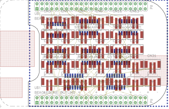
[Hudson] is looking to drive a lot of LEDs. A driver that effectively addresses kilometers worth of LED strips isn’t an easy thing to come by. So he’s in the process of designing his own BeagleBone Cape to do the work. Above you can see the board layout he’s working with. Notice the set of repeating red footprints in the center? Those are pads for 32 RS485 connectors!
Of course this is all in preparation for Burning Man where the mantra seems to be: he who has the most LEDs wins. Well, unless you’re the sort that likes to work with flames. But we digress. The scaling problem that [Hudson] is dealing with hinges around his desire not to include ridiculous numbers microcontrollers and the need to beef up the 3.3V logic levels of the BeagleBone to travel further on the data bus of the strips. By leveraging the RS485 protocol — which is designed to carry data over long distances — he can get away with a single processing unit by adding an RS485 translator at each remote strip connector. He plans to use the BeagleBone’s Programmable Realtime Units feature to address the eight drivers on the cape. But first he has to solve what looks like a doozy of a trace routing problem


Alternatively, you could buy a PixelPusher. http://heroicrobotics.com/ has ’em. Cheaper, and handles the power part of the equation too. Also supports synchronising an unlimited number of boards.
Neat. $120 for 8 strips though.
Cheaper than this cape plus a beagleboard plus whatever ungodly agglomeration you need to distribute power to all those strips.
You’re calling THAT a doozy of a trace routing problem????? Maybe a challenge for a rainy afternoon.
What’s with the trend of publishing the “I have an idea but I just started it” or “I tried this and it failed miserably” hacks lately?
“I tried this and failed miserably” is a really useful type of post for learning purposes, in the same way that a detailed postmortem of a project can help you target and improve weak areas in your team or yourself. It might even prompt someone else to try with a different approach that’s ultimately more successful.
I tentatively agree but they are rarely detailed or well documented.
You’re going to HATE what I have scheduled for tomorrow afternoon.
Turn those connectors 90 degrees and it won’t even be hard to make it as a single layer board.
RS485 is not a protocol, it is a physical interface, 30 seconds on wikipedia too much effort?
This is seriously over-complicating it, and having to drive a crapload of RS485 drivers ports via UARTs, synchronizing all, and with a protocol to address networked driver PCBs that each have configurable network addresses? Ouch.
Just use SPI which is a lot easier, far cheaper and much faster, and use the existing libs written for this stuff. Yes, you’ll have to buffer it using something like a HC244 or HC245 for long distances. Then you can very easily drive all those cheap RGB LED strips that use WS2811 controllers and similar (or even plain old HC595’s).
That’s like 95% less work overall, faster to develop, implement, code, debug and all. You could do this stuff using any old ARM dev board (mbed, lpcxpresso, rpi, beagle, etc) in one afternoon… You could even make a SPI buffer board onto protoboard in a few minutes.
Except that the micro doesn’t have enough hardware SPI ports to do that.
In a pinch, byte/word wide GPIO can be treated as 8/16 SPI ports that
share the same synchronous clock/strobe signals. You could use the big
DMA controller to blast bits from memory buffer directly to I/O ports
essentially big boys way of doing bit banging, but without using CPU
cycles.
SPI is a bus. You only need a single port; each SPI slave is selected with a single output (which isn’t part of the hardware SPI port).
Personally I would have gone for CANbus (might be even a little more over-the-top than RS485). Mostly because I think it’s cool. It does take care of a lot of the fiddly stuff he might have to worry about with RS485 though, like arbitration etc. However the communication is probably one-way, so might not be an issue.
Isn’t CANBus complication for the sake of complication? RS-485 is simple, multipoint, ancient, reliable over long distances (is canbus?), cheap to set up and cable, and has a straight-forward tradeoff between speed and distance.
You’re right, really, as I said CANbus is probably a little over the top. However many micros these days come with CAN controllers built-in, needing only a little 8-pin line driver chip to connect to the bus (as you’d need with RS485).
CANbus too is simple, multipoint, ancient (well, dates from the 80s anyway), reliable over long distances (CANopen specifies 5km at 10kbit/s down to 25m at 1Mbps), cheap to set up and cable (many people use CAT5 despite 100ohm impedence instead of 120ohm) and has a straight forward tradeof between speed and distance (as above, 5km at 10kbit/s down to 25m at 1Mbps).
I find CANbus works well for me but some people find it a little scary until they use it.
LINbus would be another option but CAN is almost as cheap these days and has supplanted LINbus in many of the situations it was previously used (the same could be said for CAN and RS485, at least in industrial situations :P).
Actually, the WS2811 isn’t anything like SPI. People just use SPI ports to send the signal because bitbanging it accurately enough (it’s a one-wire NRZ-like signalling scheme) is hard.
As a consequence, the statement about SPI being a bus is completely irrelevant.
My apologies I missed the WS2811 (I’m not familiar with it) and just seized upon your comments about SPI.
Regardless of WS2811 or not, SPI (as a bus, not a point-to-point) would be a valid topology in this case instead of the RS485, as he’s going to need some smarts on the other end of the master microcontroller interpreting the RS485 data, and it might as well be another micro as an SPI slave.
However point taken about WS2811, it would obviate the need for a dedicated micro and you could use something off the shelf.
SPI unfortunately has the drawback of being single-ended, so more prone to noise over long distances instead of RS485 (or CANbus!) which is differential.
RS485 has NOTHING to do with whether the encoded signal is asynchronous serial, SPI, or something else. The only thing it implies is a binary half-duplex channel.
A binary half-duplex channel with differential signalling. (That latter bit is important: It’s what allows it to be reasonably robust over long distances without using something fancier than binary.)
WS2811s internally buffer their output, you shouldn’t need anything external for long chains unless there is considerable distance between two LEDs.
You can also run SPI protocol over RS458 signaling.
This is something I could have used about 6 weeks ago…
Why do all the useful hacks come along too late?