We have covered many do it yourself PCBs before, but this video guide adds an easy way to sink heat from high power devices, which we think you might find handy.
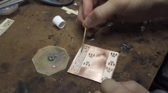
It is a very simple process that [CNLohr] uses to keep his small RGB LED projects from overheating. It starts by using a readily available silicone thermal sheet as the substrate by applying it to copper foil. He then applies a toner-transfer circuit pattern to the copper by running the pair through a modified laminator a few times. He makes note that you have to apply the plastic backing side of the silicone sheet to the copper foil to prevent the laminator from chewing it up.
After the typical ferric chloride etching process is complete, he then uses 220 grit sandpaper to remove the toner pattern. Often steel wool is used, but because of the sensitive nature of the silicone, sandpaper works better to avoid peeling up traces.
We have featured [CNLohr] before, as he does some top-notch tutorials in his workshop — which makes for both a fascinating and distracting backdrop for the videos. This one is a bit long (~20 minutes), but is very thorough and goes through the entire process from start to finish. Check it out after the break.
[Thanks Benji]


that’s remarkably clever.
how do you move in there without breaking knobs off things?
How does he possibly get anything done with such a clean work area? The kid is sick!
So the basics are: 1. Use copper, not pc board material. 2. Stick the silicone heat sink stuff to the copper. 3. Transfer and etch like you would a pc board. 4. Stick the other side of the silicone to your heat sink. 5. Build your circuit on it like you would a PC board.
His solder paste is easier to stick to the copper than mine. Chip Quick seems to be rather copper repellent and I have to work it a bit to get it onto the copper. I find solder paste the most useful stuff for soldering small things with an iron.
He actually has some pretty remarkable videos, I’m surprised his stuff hasn’t been featured before. Maybe I’ve seen his glass PCB method here but I’m not sure.
And the AVR tutorials are also pretty good.
The only people I’ve seen that have clean benches are those who:
– do everything with an Arduino and jumper cables
– specialize in test equipment unboxing
– have their workbench someplace else (the signal path)
The hackers/makers I admire the most have more disorder in their labs than me: Mike, Jeri, Ben, ….
Nicely done. This is similar to the boards used in laser printers for the controller that reflects the beam off the spinning mirror. In those they have a metal, usually aluminum, with a very thin layer of paint and then the copper traces on top of that.
The process is called Metal Core PCB
Could you please point me to a listing for a silicone sheet similar to the one used on the video? Preferably from a European or Chinese site.