An In-Depth Comparison Of Hobby PCB Manufacturers

[Icamtuf] has been working on a prototyping run of a project, which involves getting PCBs made by several low volume PCB manufacturing companies. After receiving the boards, he analyzed the results and produced an interesting analysis.

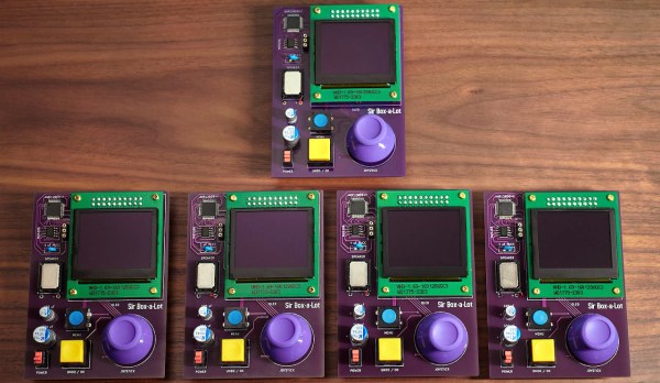
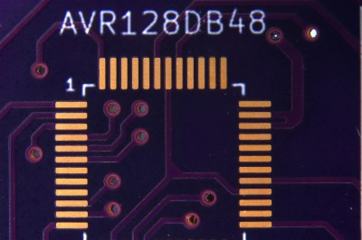
The project he is working on is Sir-Box-A-Lot, a Sokoban gaming console clone that we’ve covered before. It uses an AVR128DA28 microcontroller to emulate the original box-pushing game and drive the OLED display. He ordered PCBs from OSHPark, DigiKey Red, JLCPCB, PCBWay and Aisler.

OSHPark boards are gorgeous, but you pay for it.

There were pros and cons for each of the services: OSHPark produced the nicest-looking boards, but at the highest cost. DigiKey Red had a flawless solder mask, but a rather sloppy-looking silkscreen and shipped the boards covered in adhesive gunk. JLCPCB was fast, shipping the boards in less than 7 days, but the smaller details of the silkscreen were blurry and the solder mask was thinner than the others. The solder mask from PCBWay was very slightly misaligned but was thicker than most, and they were the only ones who queried a badly shaped hole to see what [Icamtuf] wanted to do: the others just made assumptions and made the boards without checking.

To be fair, this analysis is based on a single PCB design ordered once and it is possible that some companies were having a bad day. These were also delivered to the US, so your delivery times may vary. So, there are no clear winners and I wouldn’t make a choice based on this alone. But the analysis is well worth a read if you want to know what to look out for on your own PCBs.

30-Year-Old Macintosh SE/30 Gets A Brand New Logic Board

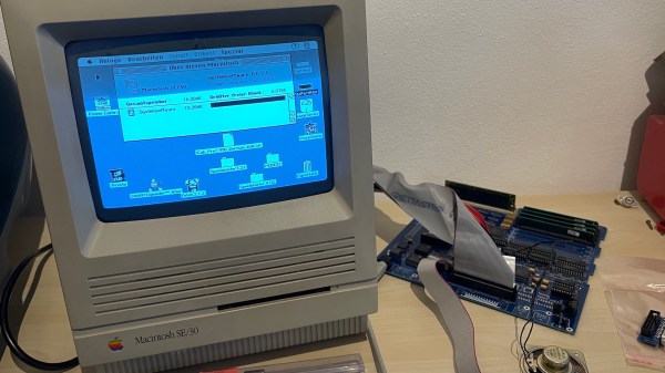
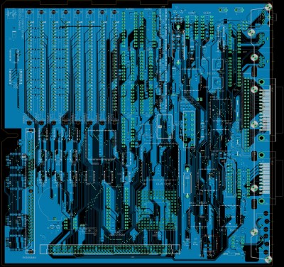
Some time ago, [Bolle] got the idea to redraw the Macintosh SE/30 schematics in Eagle. Progress was initially slow, but over the past month (and with some prodding and assistance from fellow forum frequenter [GeekDot]), he’s taken things a step further by creating a fully functional replacement Macintosh SE/30 logic board PCB.

By using the available schematics, the project didn’t even require much reverse engineering. Though he plans for more modernization in later iterations, this design is largely faithful to the original components and layout, ensuring that it is at least basically functional. He did update the real time clock battery to a CR2032 and, as a benefit of redrawing all the traces, he was able to use a 4-layer PCB in place of the costly 6-layer from Apple’s design.

The board came back from fabrication looking beautiful in blue; and, once he had it soldered up and plugged in, the old Mac booted on the very first try! A copy-paste mistake with the SCSI footprints led to some jumper wire bodging in order to get the hard drive working, but that problem has already been fixed in the next revision. And, otherwise, he’s seen no differences from the original after a few hours of runtime.

Recreating old Macintosh logic boards almost seems like its own hobby these days. With the design and fabrication capabilities now accessible to hobbyists, even projects that were once considered professional work are in reach. If you’re interested in making your own PCB designs, there are many resources available to help you get started. Alternatively, we have seen other ways to modernize your classic Macs.

[Thanks to techknight for the tip!]

Hackaday Made Me Buy It!

Reading Hackaday is great! You get so many useful tips from watching other people work, it’s truly changed nearly everything about the way I hack, especially considering that I’ve been reading Hackaday for the past 15 years. Ideas, freely shared among peers, are the best of the free and open-source hardware community. But there’s a dark downside: I’m going CNC mill shopping.

It all started with [Robin]’s excellent video and website tutorial on his particular PCB DIY procedures. You see, I love making PCBs at home, because I’m unafraid of chemistry, practiced with a rolling pin and iron, and super-duper impatient. If I can get a board done today, I’m not waiting a week, even if that means an hour of work on my part.

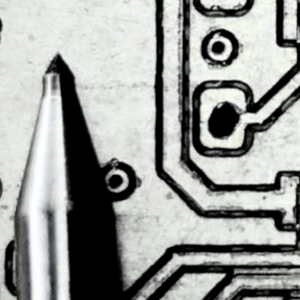
Among other things, he’s got this great technique with a scriber pen and a cleverly designed registration base that make it easy for him to do nearly perfectly aligned two-sided boards with a resolution approaching etching. The ability to make easy double-sided boards, with holes drilled, makes milling attractive, but the low resolution of v-cutter milled boards has been the show-stopper for me. If that’s gone, maybe it’s time to take a serious look.

And heck, making PCBs is really just the tip of the iceberg for what I’d want to do with a CNC mill. Currently, I do dodgy metalworking with an x-y table and a drill press, some of which may someday land me in the hospital. But if I had a mill, I’d be doing all sorts of funny wood joinery and who knows what else. I lack experience with a mill, but coincidentally, we just had a Hack Chat on Linux for machine tools this week. You see? It’s all conspiring against me.

The only question left is what I should get. I’m looking at the ballscrew 3040 range of CNCs, and maybe upgrading the spindle. I’d like to mill up to aluminum, but don’t really need steel. What do you think?

Why Wait? Just Plate Your Own PCB Vias

[Jan Mrázek] is a pro when it comes to rolling his own PCBs. He can crank out a 6/6 mil double-sided PCB in 45 minutes flat. As a challenge to his prowess, he decided to experiment with plating through-hole PCBs at home, because sometimes you just can’t wait for China to deliver the goods.

The key here is to make a non-conductive surface—the walls of holes drilled in a sheet of copper clad–conductive. While there are some established ways of doing this at home, the chemicals are difficult to source. When his local supplier started stocking colloidal graphite paint, which is used to prevent ESD and fix non-working remote control buttons, he decided to try it.

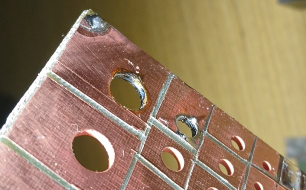
[Jan] drilled up a board with holes ranging from 0.1mm up to 8mm, polished it, and gave it an acetone bath. He sprayed each side with graphite and cured it at 100 °C for 20 minutes. At this point, wall hole resistance measured 21 Ω. [Jan] wet-sanded away the graphite and set up an electroplating bath. Right away, he could see a layer of copper forming on the holes. After 90 minutes, he polished the board again and separated the vias to prepare for the real test: solder. This time, every hole except the smallest size reported a resistance of 0.1 Ω. But they all sucked solder through the vias, making this experiment a success.

[Jan] concluded that this is a simple and effective process, but is rarely worth the effort. We wonder how the simplicity of this method compares to drilling wells instead of holes, filling them with conductive ink, and then drilling the rest of the via.

Via [Dangerous Prototypes]

A Heart For His Girlfriend

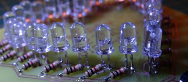
[Decino] made a nice LED animated blinking heart box for his girlfriend. That’s a nice gesture, but more to the point here, it’s a nice entrée into the world of custom hardware. The project isn’t anything more than a home-etched PCB, a custom 3D-printed case, a mess of LEDs and current-limiting resistors, a shift register, and a microcontroller. (OK, we’re admittedly forgetting the Fifth Element.) The board is even single-sided with pretty wide traces. In short, it’s a great first project that ties together all of the basics without any parts left over. Oh, and did we mention Valentine’s day?

Once you’ve got these basics down, though, the world is your oyster. Building almost anything you need is just a matter of refining the process and practice. And if you’ve never played around with shift registers, a mega-blinker project like this is a great way to learn hands-on.

Not everything we write up on Hackaday has to be neural nets and JTAG ports. Sometimes a good beginner project that hits the fundamentals with no extra fat is just the ticket. What’s your favorite intro project?

Blob Grid Array Technique Mounts Board-To-Board

[Howard Matthews] mills his own PCBs, and man, does he hate drilling through-holes. Manually changing the bits between engraving and drilling after isolation routing? What is this? The stone age? [Howard] decided to rethink his DIY PCB manufacturing process, and came to one essential conclusion: Only a fraction of these drills are actually necessary.

Continue reading “Blob Grid Array Technique Mounts Board-To-Board”

Toner Transfer And Packing Tape

The toner transfer process of producing PCBs has evolved tremendously over the last few years. It started out by printing PCB layouts onto magazines with a laser printer, then some clever people figured out that glossy inkjet photo paper would work just as well. Now there’s a new substrate for you – packing tape – and it seems to work pretty well.

[David] was designing a cheap board for a robot kit for a workshop and needed 100 tiny PCBs. They were simple boards, and perfectly suited for home PCB manufacturing. He started off by printing directly onto glossy magazine paper, but this wasn’t an ideal solution. During one run, some of the toner landed on the packaging tape he was using to secure the boards. A bit of serendipity came into play and [David] discovered packaging tape is usable in the toner transfer process.

The technique is simple enough: put some packaging tape on a piece of paper, print a board layout (reversed!) on a laser printer, and go through the usual clothes iron/laminator/etching process. [David] is actually using a hair straightener for transferring the toner over to the copper clad board – interesting, and in a pinch you can use the same tool for reflowing SMD components.