From what you would gather from Hackaday’s immense library of builds and projects over several years, the only way to do PWM is with a microcontroller, some code, a full-blown IDE, or even a real-time operating system. To some readers, we’re sure, this comes naturally and with an awesome toolchain it can be as easy as screwing in a light bulb. There is, of course, an easier way.
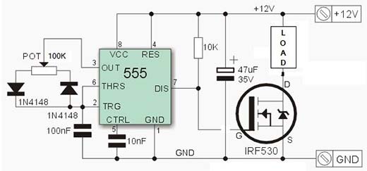
[Jestin] needed to vary the current on a small 12 Volt load. Instead of digging out an in system programmer, he turned to the classic 555 chip. With a single pot, it’s easy to vary the duty cycle of the 555 and connect that to a MOSFET. Put a load in there, and you have a very easy circuit that’s a fully functioning PWM dimmer.
If all you have are a few scraps in your part drawers, this is a very, very easy way to set up a dimmer switch. We’re also loving [Jestin]’s improv aluminum tube enclosure, as seen in the video below.
[youtube=http://www.youtube.com/watch?v=JJ-Kus7d57A&w=580]


Its easy to overlook analogue parts in today’s world of microcontrollers. But learning about timers, op amps, and regulators, you can really extend the possibilities of your uC. IMHO of course.
Absolutely true. Implementing things like band pass filters is difficult using 8-bit uC
I’m sure this looks weird to more software oriented people, but world existed before MCUs. Nice little aluminium case.
Used a 555 and a 3055 NPN power transistor to run a motor in the 70s. But I used the 555 the usual way ’round with a resistor in series with out driving the base and the pot varying charge time. These days, why mess with all those parts when a Tiny45 costs next to nothing. It was convenient that a 555 would work at 12v.
The main reason I can see is simplicity. If you want manual control with a knob like that, you would still need the mosfet and the rheostat (or and encoder). Add in the mcu and you still have the same number of components.
Then you have to write firmware to translate the input from the knob to output PWM. While this *can* give you more flexibility in the design (you could program different gain settings, or add in slew rate limiting, etc…all of which could be easily modified in code or on the fly with another connection) , if you don’t need that flexibility, it just introduces complexity and creates holes for bugs to hide in.
Right, but if you connect a k type thermocouple to A0 you aren’t going to see much. Run it through a halfway decent op amp and blam! Your fireball throwing arduino powered yatzee predicting coffee mug reads the temperature of its glass kiln
Not to mention, this is a great beginner circuit for learning electronics the old-school way.
Although I prefer the variant where the output pin of the 555 is used to drive the mosfet.
It seems to be better suited to drive a wide variety of mosfets.
‘coz I don’t have a Tiny45, nor a programmer, nor a want to program an extremely simple function and have to write code when i can just swap a component. Also, to some people, mcu’s are intimidating, and also learning analog electronics is kinda key, no matter what you’re doing.
Honestly these days I beg to differ. I have colleagues who are chemical engineers who’s experience in electronics consisted nothing more of making a lightbulb light up in highschool physics who are playing with Arduinos due to their braindead ease of use. I would argue conceptually to someone who isn’t an electrical engineer it would be easier to setup and program an Arduino to do PWM than it would be to understand how the above 555 timer works. Hell even if you do understand how a 555 timer works an antiparallel diode circuit with resistance and capacitance is an incredibly daunting circuit.
And that’s one of the keys to getting something out of a hobby, an understanding. Any idiot can copy a circuit off the internet, many an idiot do and get horrendously stuck when it doesn’t work first go. In this case an Arduino is an all mighty all powerful black box where you plug in power in one end, and a mosfet ehh I mean switching thingy in the other and you have a full understanding of what is happening to easy to follow code.
Now this doesn’t necessarily apply to an ATTiny45 that you program yourself, but for a lot of the newbie crowd microcontroller = Arduino = very bloody simple.
When any idiot can do it, any idiot will do it. And then before you know it we’ll have retarded arduino code running safety-critical machinery where three transistors would have done it and never crashed because of an idiot mistake.
The guy who designed the three-transistor solution had to really know his shit to get it that elegant and robust, and the guy who wrote 8kb of arduino code to flash one LED and switch a relay is not to be encouraged.
If the guy that designed the 3 transistor solution comes to me and says “well, an AtTiny is cheaper in production” I’ll trust him and go with his solution.
I’m all for people hacking away and learning, expanding their horizons, whatever… but it’s important to know the difference between a hack that mostly works and something that’s right for the job.
Totally agree with this. And even in non-safety-critical applications, you see this backsliding of knowledge daily. Instead of precision engineering, you get sloppy crap that’s held together by an MCU.
The stupidity infects everything. Look at audio receivers today: I have a nearly “top of the line” receiver with probably nine amplifiers in it… but I can’t play the same source through three speaker pairs. I mean WTF, that only requires a couple of “analog” SWITCHES!
Heh, I like the title. All viewpoints accounted for. :)
I noticed the same thing [Tom the Brat] did, the 555 is not being used “the usual way ’round” here. I’d think the output pin would be more suited to efficiently switching the MOSFET’s gate capacitance. Is there some other advantage to this configuration?
You could get a simple comparator IC to do it, IMO would be a simpler circuit.
The 555 is a universal IC that can be used for many things, so instead of stocking many different IC’s, a 555 plus some common axillary parts is often a more sensible thing to keep in stock.
The 555 _is_ a comparator at heart, not to mention being very, very cheap and robust.
I think the ‘backwards’ way he used is the method shown in the datasheet.
No, I checked the TI, Fairchild and National datasheets. I’ve never seen that. Is he a mad genius, or is there really a version of the datasheet that shows this?
This circuit was featured on an old issue of elektor magazine. And i’ve seen it a couple of times on other sites with variants.
Wow, what a coincidence! I just built one of these things today, before reading the article.
If the load is even slightly inductive, a freewheeling diode across it would be a good idea, otherwise the MOSFET will be forced into avalanche breakdown every time you turn it off. Charging the gate through a 10k resistor is horrible, it causes huge switching losses, why not use the output instead? One of the great features of the 555 is that the output can source and sink 200mA! In any case, a resistor in series with the gate is required to limit the current to protect the output transistors of the poor 555, and it will dampen gate oscillations (wires are inductive, you know).
As a final note, it’s better to place a diode in series with 555’s power supply, and give it a dedicated buffer capacitor and decoupling, to prevent the transients caused by the switching from falsely triggering the 555.
I once had a 240V dimmer that used a 555. It was old and was the only dimmer switch that I have ever seen that had its own fuse holder!
Here comes the most stupid comment, (pardon me for that) However, I do not understand, why can he use a little higher (power) rated pot. directly in load path and do away with all the reg/cap/diodes/FET and 555? Since its just 12v and load does not seems to be too heavy and control is a simple knob??
Because the pot acts like a resistor and dissipates the excess power as heat which is not as efficient. Using a pot also lowers the voltage where as the 555 pulses the power limiting the current while maintaining the same supply voltage.
Not just “not as efficient”, you need a much larger, more expensive wirewound pot. He’s driving a 35W lamp with it. A quick filter of Farnell to >=8W shows the cheapest power pot at £25! (~$40)
http://uk.farnell.com/jsp/search/browse.jsp?N=204275+110116718+110112314+110018464&No=0&getResults=true&appliedparametrics=true&locale=en_UK&divisionLocale=en_UK&catalogId=&skipManufacturer=false&skipParametricAttributeId=&prevNValues=204275&mm=1000635||,&filtersHidden=false&appliedHidden=false&autoApply=false&originalQueryURL=%2Fjsp%2Fsearch%2Fbrowse.jsp%3FN%3D204275%26No%3D0%26getResults%3Dtrue%26appliedparametrics%3Dtrue%26locale%3Den_UK%26divisionLocale%3Den_UK%26catalogId%3D%26skipManufacturer%3Dfalse%26skipParametricAttributeId%3D%26prevNValues%3D204275
Jesus Christ!! Farnell are rip-off bastards! 25 quid was the most expensive 60w pot I could find!
http://www.rapidonline.com/Electronic-Components/Potentiometers-High-Power-Wirewound-10-520164
Yeah… Farnell may be expensive but Rapid are the 50p shop of the electronics world, cheap is cheap for a reason…
the 555/transistor doesnt really limit the voltage or current, it just changes the duty cycle, so the average current is lower, but its just switching between no current and full current
look here http://www.dprg.org/tutorials/2005-11a/ it extensive explains including inside of the 555, shame hackaday already drops posting ease by stupid credentials/ loging before posting.
I had to add a dimmer to an LED controller once. The LEDs were already PWM’d from a microcontroller but it had no brightness control. I ended up making a similar circuit to the above and just used AND gates to connect the controller and the 555. I expected to see some warbling in the brightness but with the 555 frequency set up about 3-4x that of the PWM controller it ended up working really well.
knew i had seen something like this before……
Ahem.
http://hackaday.com/2008/11/16/simple-pwm/
:)
very close though he swapped the ‘out’ and ‘dis’ pins.
555’s are so underrated these days. When I was on the staff for a LARP I whipped up a few dim-able glowing costume pieces, all driven by a humble 555 driver circuit.
For every AVR I used in props, I probably had 2 to 4 simple effects I drove w/ discrete parts.
I need to use a similar circuit to control 220V AC lamp throw a full wave rectifier. Actually I don’t know if the AC ground (which is the source of the MOSFET) and the DC ground (which is the ground of 555 or a micro controller) have to connected to each other or not??
I built a custom PC case from a 1939 Philco radio cabinet. I wanted to use a large 24 volt PWM reverse impeller blower as a primary fan, but the PWM standard it uses is not compatible with the PWM used by PC case and CPU fans.
My solution was to feed the PWM from the mobo through an optocoupler, to isolate it from my 24 volt circuit, and generate a DC voltage off the PWM. I then created a triangle wave generator with a pair of pots to set the upper and lower peaks of the triangle wave. I feed the triangle wave (set to the blower’s PWM frequency) and the PWM derived analog voltage into a comparator. The higher the voltage, the higher on the triangle wave the output switches. The lower the voltage, the lower on the triangle wave the output switches.
This gives me a voltage controlled PWM generator that has pot adjustable upper and lower PWM range limits!
The best thing to fit in a 1939 Philco radio cabinet is a 1939 Philco radio.
Hi, the original circuit diagram is in:
http://www.inventable.eu/2013/04/18/63_led_dimmer_555/
Cool, with a mosfet 04N60C3 works fine
Drive a LED strip
Tks ;)
Can I use a more standard (cheaper) transistor if using pwm for less than 1a load? I’m running a nichrome coil and a dc 3v dc motor (fan) in parallel, off a 5v 2.5a power supply. I haven’t built yet, but would assume trial and error with the coil could easily be tuned to around 10w consumption. The remaining 2.5w is ample for the dc motor but will need voltage lowered from 5v to 3w, with the most efficient way being a PWM like this.