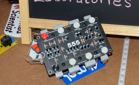
The 555 timer chip is a ubiquitous piece of technology that is oft-considered the hardcore way of doing things. Of course, the old timers out there will remind us that discrete transistors are the badass way of doing things, and tubes even more so. It’s not quite at the level of triodes and transformers, but Evil Mad Scientist’s discrete 555 kit is still an amazing piece of kit.
Instead of transistors and resistors etched into silicon as in the OG 555, [Windell] over at EMS turned the basic circuit inside a 555 into a mega-sized version using discrete components. Your parts bins need new scale if you’re going to work with this and other up-scaled hobby electronic components.
Although the integrated stand that makes the whole package look like an overgrown DIP doesn’t break out the signals on the board, it does include some neat screw terminals for alligator clips and bits of wire so this kit can be used in a circuit. Because it uses discrete components, you can also take a meter or scope to check out how a 555 chip works from the inside.


Mhhhh… I like the idea, but… the wiring is a bit deceptive. I’m really new to all this stuff and if I imagine that this should teach others, I would say: Design it like the shematics. For Example the resistors looks strange aligned. Make them look at each others like you would do on the shematics. This way pupils could point at the shematics and see the exact same pattern in the Layout. They set up boxes for stations, what is great… but they have so much space, they could make it even more intuitive if they could align the components a bit better. Or even print the whole circuit in the soiderstop mask.
Never the less: It’s a good project. This will help teaching and I’m sure this device can improve over the next years even more. Good Job!
I totally agree about printing connections on the soldermask and keeping it as similar to reference design shape as possible
Maybe that idea could be taken to even another level. Print, draw or silk screen the schematic right on the top of the thing, with each part and connection in the schematic lined up with the real thing.
I built a ham radio transmitter (Michigan Mighty Mite) this way once. I traced the schematic onto a block of wood using carbon paper, then I etched it in with a wood burner. I nailed brass nails into the wood at each connection point then I soldered the parts to the nails as well as wires between them.
Bravo, Gentlemen. A very novel and creative idea…
It’s not a 555, it should be called a 4.7/4.7/4.7… :-)
Nice. Got a chuckle out of “disintegrated circuit”.
But what you’ll learn from probing it in realtime is somewhat dependent on the quality of your test equipment. And those at a level who would find such an exercise educational, typically have limited equipment at their disposal. So I think simulating this in SPICE instead would be more informative. Though it could also be argued that learning to analyze a real circuit *despite* the limitations of your test equipment is also a valuable exercise.
To [Wonko the Sane] – at least it doesn’t use 6K resistors!
Great educational tool….
Agree with the comment about printing the schematic on the top of the board and aligning the components to suit, it’s the first thing I thought of too. There’s heaps of space to allow that. The concept is great and it’s a nice kit and all, but they should go a version 2 layout that really would be better to learn from.
Now that’s cool. Utterly pointless + quality execution makes for a very cool hack.
Will it fit in this: http://www.evilmadscientist.com/2011/555-footstool/?
Reminds me of a project I did back in school. We built an 8 bitter adder with discrete transistors. I was a comp science major. Two hundred or so transistors later and the completely wrong resistor values, we had an adder that took about 8 amps to operate. Good times.
Looks like the project site is still up.
http://compsci02.snc.edu/cs225/2004/alu/website/index.html
Not sure even the purist would want to use tubes for a timer, for audio OK but for anything else they seem a real pain.
I love the concept! It’d be interesting to see a more ICs built from discrete components like this, as teaching tools.