It may be a failure but it sure does look cool. [Scott Lawrence] had a fair number of EPROM chips on hand and decided to get rid of the traditional eraser and programmer in order to play around with the concepts using his own hardware. He was met with disappointment at several steps in the process. No worries though, each of these upsets sent him back to the drawing board and he learned way more than he ever would have if it had actually worked. It’s fair to say this failure was highly successful.
You’ll want to check out both posts revolving around this hardware. The initial idea came when looking through the transparent crystal on the top of the EPROM chips. The die inside looks like a tennis court to [Scott] and he started wondering what the bits themselves look like as they are reset by ultraviolet light. He conceived of an Arduino add-on board that could both read and erase the chips. The I/O demands of this design led him to actually fabricate a daughter board to use with the MUX shield for Arduino. This is fail number one as the workings of that shield didn’t fit the needs of the project. The redesign also had him scratching his head, but eventually he ended up settling on the use of some shift registers to expand his pin count.
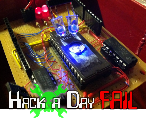
With that design idea he forged ahead, building the Arduino shield seen above. Those part numbers aren’t the shift registers you’d expect. He ended up going a bit different route by salvaging these 74LS393 chips from an old Amiga add-on board. This worked like a charm. The dual UV LEDs for erasing the chip didn’t work even a little bit. His dreams of visualizing bits as they are erased have been dashed, but he does look on the bright side that he now has a way to read EPROM using an Arduino.
 Fail of the Week is a Hackaday column which runs every Wednesday. Help keep the fun rolling by writing about your past failures and sending us a link to the story — or sending in links to fail write ups you find in your Internet travels.


Needs moar cowbell, er brightness.
No, needs less – less wavelength ;-)
UV-LED ~ 400nm
UV-Lamp ~250nm
—
But really an interesting approach 8)
yep, common mistake, UV LED’s DO NOT EMIT UV LIGHT!!!!
want a UV LED? then your looking at £200+
Just stick a 20W fluorescent lamp with a proper ballast and control it with a relay. I’m actually interested in these results!
That! I’ve seen a few eBay auctions selling UV LEDs for erasing EPROM but just about all UV LED that costs pennies are capable of UV-A only. EPROM needs UV-C and UV-C is not something you want sitting around in random LED bin. UV-C can cause permanent blindness easily.
Good thing the project failed with LEDs, had the LED worked for erasing the chip, the user would have been blind and posting this fail using brallie keyboard in a hospital somewhere.
I still don’t like the big red letters saying FAIL. It looks way too unfriendly.
Needs shorter wavelength, like germicidal lamps. UV LEDs aren’t that wavelength because they would burn your eyes out.
Also I believe they’d break down the encapsulant used to make the body of the LED itself…
UV-C sources use fused-quartz envelopes for this reason.
Hi, I tried this way back in 1998 with the RS GaN blue LEDs which would emit UV when pulsed.
Needless to say it didn’t work though I was able to demonstrate fluorescence effects etc.
Also tried with a proper 395nm UV 0.5W LED when they became available on a PIC 12C508JW and this also didn’t work.
These really need 290nm or below to erase.
will sunlight do it?
Yes. it will erase a eprom but it takes several days. Make sure you dont put it behind a window, it must be outside. Typical glass absorbs UV.
it does but you will need to leave it outside in direct sunlight for plenty of hours, even days, depending on where you are located and the season..
Several years ago that was the only method to erase EPROMs I had and did it often.
With about 5h/day of outoors full sun in the summer of the sunny south usually took 3-7 days depending of the EPROM.
Checking every day you could see the bits dissapearing, but you checking it under the sun makes it look erased when really isn’t because the transistors malfunction.
That effect could be used with 4116 drams to make a crude high frame rate bw binary cammera.
Yep, as other have said: needs a much beefier UV-lamp. I suspect the ones commonly used for PCB fabrication wouldn’t work either (those that’s bad for your health but not that bad).
One thing to look out for here: the small wires that are laid out on top of each other is not all that great. When soldering one of them, with the other resting on it, can potentially melt the plastic around the cable. The risk of this happening is greater than you might think at first, and it isn’t noticable should you not lift the wires and inspect them. Just two small wires that has bonded together doesn’t look like they were molten together at all, until you look carefully at its contact (separating them is a must, detecting this is harder than it might sound when explained).
I’ve had many shorts due to this :(
I’ve wired many boards this way. I learned quickly: solder the wires with them up in the air. Once they cool, THEN you can press them down and make it look neat.
I looked into building a EPROM eraser and determined that the germicidal fluoro lamps are the best way forward. You might be able to erase with the GTL3 lamps, which look a lot friendlier to use if you build a nice aluminum reflector.
Yeah, I’ve seen this done with a UV pacifier sanitizer. Now that I have friends with young kids i come to find out the parents are supposed to put a dropped pacifier in their own mouths first — apparently the theory is that this technique helps build immune systems.
At any rate, if you can get a hold of one of those sanitizers, scrap it to use as an EPROM eraser.
I never heard about it helping immune systems, but most mums, my own included, put a dropped dummy (“pacifier”) in their own mouth first. I think it’s a motherly instinct, perhaps chimps do it with dropped bananas. It goes back at least to my own mum doing it in the 1970s, and there weren’t so many bullshit holistic health claims round back then.
Personally I’d keep a stock of new ones and leave the old behind, but that’s obsessive-compulsive disorder for you.
You can leave the EPROM in the sun (not behind a window). Depending on
where you are and the season, it will be erased in half a day to a few
days.
Just leave them in the sun for some days, I did that many years by a mistake and the Eprom was empty … lucky I had another one I coud copy back :-)
I got a cheap UV-C discharge lamp used for carp ponds to erase EEPROMs
Like ebay item 150846848777
Just take care of your eyes
Failure is all part of progress. You have to know what not to do in order to figure out what the right way is….unless you’re the federal government.
Maybe the 3rd generation shield will use some LEDs from the good folks at Roithner Laser: http://www.roithner-laser.com/led_deepuv.html
I’m guessing those LEDs are both dangerous to work with and expensive.
Only around $475 a pop.
For what it’s worth, for all of you suggesting that I use a different true-UV, shorter wavelength LED, I do mention the issue with the wavelength in the second article. In my estimations, with the LEDs on there, it should take between a half year to a year to erase the device. Far from optimal. The next thing I still need to do is to drop the board inside my proper Eraser. And the point of this project wasn’t just to erase the ROMs… It was to dump them multiple times during the erasure process, then represent the bits as a bitmap graphic, to be animated.
I think the next thing you need to do is measure how long it actually takes to erase with those LEDs. 6-12 months worth of testing is pretty hard core.
I would love to see this!
Is there a way you could wire up an EPROM while it’s in the eraser, so you can watch the bits blast away? Maybe partly disassemble the eraser without breaking it, if it’s possible. It would be interesting to see if it’s anything other than random.
that’s exactly the plan. I’ll have the device inside the eraser (with the safety switch disabled, if need be). In my experience, with my eraser, it takes between 10-12 minutes to erase any EPROM i’ve put in it.
You could use an LED, though the standard radioshack UV ones will not suffice. These guys are going to be one of the only groups that will sell you one: http://www.s-et.com/
You are way better off getting something like one of the 10.5v Ushio 3000022 UV bulbs.
Small UV fluo (clear fluo tube) would work I guess. You can also use common mercury street light but you have to carefully break outer white baloon, and keep inner UV tube in one piece. Of course you have to cover it with something or say goodbye to your eyes.
When i play around with discharge arcs or other potentially dangerous light, i like to view them through a camera. that way i will only ruin a digital camera, not my eyes.
Try a camera flash gun – I used a device based in this method during the late ’90s
The device was a flash tube in a ‘gun’ with a quartz window and it flashed about 10 times a second – it took less than 10 seconds to wipe an EPROM.
damn HaD ate my comment but yeah i was also gonna suggest a modified camera flashlight just make sure to remove diffractor/uv filter and if that’s not enough you could try beefing up the cap to increase current density and shift the emitted light spectrum slightly.
you might wanna give mercury vapor lamps a try they emit a fair amount of UV if they are not coated with phosphor or other stuff (tanning bed lamps anyone???)
This brings back fond memories.
Years ago (probably around 2002) I got two Epson HI-80 pen plotters. One worked (beautifully), one didn’t. They were really cute – as far as I remember, simple serial interface with built-in commands for drawing lines, arcs etc. I eventually determined that the program EPROM in one had failed, because swapping the EPROM from the good one worked.
I then delved into building an EPROM reader (which I think used a stack of shift registers driven directly from the parallel port) and even managed to disassemble the program inside the chip (the processor was an old NEC device). I never got around to actually programming the replacement, but I did find an extremely effective way of erasing it:
Carbon-arc torch.
Yep. I used one at the time for brazing (before I got an oxy-propane rig). Holding the torch about 1ft from the chip, it was erased in under 10 seconds!
Brings back different memories for me. Back when some of those chips were made, I was working at AMD in the non-volatile memory group, and on those specific chips (AM27C128, AM27C256, etc)
Hi: At a pool supply, aquarium supply or eBay you can get UV sterilizer lamps for around $10. They are clear with no phosphor coating and some are T5 format and fit in a small under-cabinet type fixture. Cheers, Mark
Alternate idea, make a one atmosphere glow discharge “plasma panel” using 80 wire HDD cable with alternate wires connected together and two out of phase CCFL inverters.
The basic method is the same as used in those ignition coil based OAUGDP setups but using CCFLs makes the whole thing a lot more compact.
You want to aim for about a 120-400Hz frequency difference, also worth encapsulating the ends of the cable in HV 3 hour Epoxy to prevent arcovers.
Don’t use the 90 second stuff as it has metallic impurities and will fail in short order.
what about a laser diode from an old cd-rom writer? but yes, this will be a little dangerous, the power rating is high
Wrong end of the spectrum – In true CD writers you will find an infrared, not ultraviolet laser, in DVD writers a red one usually combined with an infrared one for CDROM media. More often than not, the devices used have no markings and/or are integrated into some kind of IC/hybrid so a datasheet will be difficult to find. The IR ones also are very dangerous to mess with since they are very capable of causing eye *injury* before eye *pain* tells you that looking into them is a bad idea. Another warning to people unfamiliar with laser diodes: One CAN NOT just operate, say, a 100mW device at 1mW and then turn the power up gradually – at 1/100th the rated current the laser diode will behave like a bad LED and only jump into lasing operation – in this example, probably at a power level that will already be very unsafe to your eyes! – once a certain current threshold is reached.
“…..jump into lasing operation – in this example, probably at a power level that will already be very unsafe to your eyes!”
Eh, no. Have a look at any plot of optical output power versus input current (for example http://www.repairfaq.org/sam/Blu-ray/site1/ps3diode-images/diode-plot.jpg). Yes, there is a threshold current (28mA or so in this case), above which the output power starts increasing more _rapidly_ with input current, but there’s no sudden jump in the output power.
I admit to simplifying – but from a safety standpoint the behaviour shown in the graph you linked to is almost as dangerous to someone not aware of it. 25mA “most likely harmless – do not take my word for it BEING harmless, I AM not an expert on wavelength vs physiological effects!”, 35mA “likely painful, I would rather assume a risk of permanent damage than being careless at that power level”.
Uv laser, probably to expensive. Bluray laser diode probably not close enough. Anyone know about an led from a fibre optic network equipment ?
No, fibre optic network equipment light sources are all IR, well over 1000nm
Correction: … except 850nm wavelength, but it’s also IR.
…with some types of fibre links also using visible red lasers or LEDs. UV-C wavelengths would not be very useful with glass fibers since, as has been stated earlier, most glass is not transparent to UV-C. PS, I can highly recommend reading the Dov Frohmann Oral History from the CHM site when it comes to EPROM technology… and what the original idea was on how to erase them.
I like the idea of a micro being used to slowly pulse a UV light on and off, wiping its own memory, effectively killing itself in the progress…
That sounded way more macabre than I meant
So THAT’S what went wrong with my computer-controlled EPROM eraser!
This is quite interesting… I’ve been working with EPROM sometime, but never really dwelled deep into the workings.