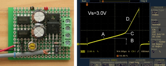
Back to the basics: there are three kinds of passive electronic components: Inductors, Capacitors and Resistors. An inductor can be easily built and many types of core and bobbin kits are available. However, characterizing one hypothetical coil you just made is quite tricky as its inductance will depend on the measurement frequency and DC bias current. That’s why [ChaN] designed the circuit shown above.
As you may guess, RF enthusiasts are more interested in the inductance vs frequency curve while power circuit designers prefer inductance vs load current (for a given frequency). The basic principle behind the circuit shown above is to load an inductor for repetitive short periods and visualizing the current curve with an oscilloscope connected to a sense resistor. When loading the inductor, the current curve will be composed of two consecutive slopes as at a given moment the coil’s core will be saturated. Measuring the slope coefficient then allows us to compute the corresponding inductance.
[Via Dangerous Prototypes]


http://en.wikipedia.org/wiki/Memristor
Varistors, pots, poly switches, thermistors, thermo-couples, diodes, zeners, piezos, peltiers, speakers, variacs, tuners, voltaics, transformers, antennas, wave guides, photo diodes, buttons, switches, bulbs, motors, relays and on and on and on lol
Nice and simple idea, and a clean build.
(by the way, ChaN is also responsible for the FatFs module http://elm-chan.org/fsw/ff/00index_e.html)
My Wii thanks him for that module.
This is a great idea and very useful. It takes a lot of guess work out of designing things. Most of the time the test conditions done on data sheets don’t match the load and frequency needed for a design. This will allow people to dial a design in much closer to optimal performance. :) kudos and a high 5!
The featuring of more home brew test equipment, and test equipment accessories gets my vote. Always.
Nice, simple, clean, it does exactly one thing, and looks like it does this well.
This is not just useful to check manufacturer datasheets, it’s also a great tool to check your custom-made inductors, or to determine the specifications of an unknown inductor from the junk bin. Most of the time, the larger inductors (toroids and such) have zero markings; no brand name, no type number, and even the color of the core won’t give you any certainty about it’s material or properties.
Sure, you can measure the resistance and inductance of an unknown coil, but anyone who has ever used an LCR meter knows the frustration of testing on several different frequencies and getting wildly varying measurement results.
Personally, I’d have use a better MOSFET though (I’m guessing this one came from the junk bin), but unless you’re building rather beefy power supplies and such, 60A should be more than enough to test your inductors with.
I’m not entirely sure, but I think some magnetic cores can be permanently damaged by excessive overcurrents; maybe an adjustable current limiter would be a good idea? Of course, you could also start at a very small duty cycle and gradually increase this to prevent excessive overcurrents.