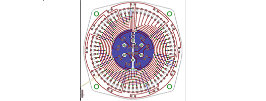
[Bryan] has been working on a very nice analog LED clock circuit, but when it came time to lay out the parts in Eagle, he was somewhat miffed by the inability to create designs in his Eagle boards. Eagle is a fine tool for laying out circuits, but when it comes to making strangely shaped PCBs, Eagle just isn’t the right tool.
The solution to this problem was to create the board outline in OpenSCAD. The desired shape of [Bryan]’s clock was easily designed, but importing the shape into an Eagle layer was another matter entirely.
OpenSCAD, though, can output 2D shapes to the DXF format. Getting the DXF board into Eagle required [Bryan] to write a script that outputs Eagle WIRE commands. Pasting these commands into the command line gave [Bryan] a perfectly shaped PCB.
Since DXF is supported by every drawing package on the planet, [Bryan]’s 20 line script could also be used for much more intricate designs. If you have an incredibly complex Illustrator drawing that deserves to be a PCB, it doesn’t get much easier than tossing it through a script.


Or he could have done it with KiCAD:
http://andygoetz.org/2012-9-13-complex-shapes-in-KiCad.html
Very nice tool, thanks for mentionning it!
So what you’re suggesting is that he learns two new programs, KiCAD and QCAD and then re-draws his whole circuit rather than either using the pre-written dxf converters or using his own?
No, what I am saying is that if he was already using KiCAD, which is totally free of restriction, and entirely open, he would have had access to an easily parsed/generated notation for board outlines. He could probably have written a small Python script to generate the board outline in that picture directly to a KiCAD file.
OpenSCAD produces DXF just as QCAD does, so either would be fine.
I am pro-KiCAD because it is open and free. Any post I see that promotes Eagle needs to be countered by pointing out its closed and restricted nature.
It’s also very easy to generate a python script to draw any object in Eagle.
* Up to 100 x 80 mm (this got me to change to kicad)
* Only 2 layers
* Everytime you need to create a part, or make small changes to an existing one it’s a complex task
* No DRC while laying tracks
* One sheet and no sub-sheets
* No usefull 3D viewer
But people are adverse to changes even when there is clear benefits on the other side, but remember that engeneers need to keep learning new things every day or become obsolete
Most of those restrictions do not apply when you get the paid version. What’s the problem with making parts ? I’ve never thought this was particularly complex.
They can get me to consider using KiCAD whenever wires adhere to components by default.
That anyone would consider that an optional feature for an EE CAD software boggles.
Have you tried to grab (was it G?) instead of moving (M)?
there are DXF to ULP and DXF to SCR importers, I used one last week.
example: http://www.cadsoftusa.com/downloads/file/dxfimport1_3.zip
I use TopoR (topological router) from eremex to route PCB. It supports EAGLE .brd import and allows to create any board shape.
Example: http://eda.eremex.ru/cms/f/434663.jpg
Man, TopoR is very powerful, I’ve tried it a few times and was quite impressed. But those tracks… They look like they’re drawn with a marker pen. By a squirrel. While drunk. :))
I just assume it’s OK, and the only reason to such reaction is a habit. We are too used to the rectangular tracks.
The problem is that clients are used to rectangular tracks too :( I can’t deliver a PCB with anything else than straight and 45 deg lines…
The nice thing with Eagle V6 is that board, schematics and libraries are XML, and you can go in with any text editor to tweak things. I’ve used this to get components lined up and exactly spaced, for instance. Of course, you can royally fsck things up that way too, so always work on a copy. And don’t edit the file while you have it open in Eagle.
So in this case, if there wasn’t an obvious way to get the desired shape into the board (through a SCR or ULP), I would look at the wire statements for the dimension layer, determine the necessary X-Y pairs for the contour, turn those pairs into correct XML lines, and replace the existing dimension lines with the stuff I just generated.
Another good reason to switch to KiCAD is that CERN is now supporting it. There are some major upcoming updates.
FWIW, I’ve been working on a Ruby gem for reading and writing Eagle files to solve exactly this problem.
Here’s the code in case anyone is interested: https://github.com/bfoz/eaglecad-ruby
I never say this, but this is the first time: “Nothing new here!”
You can figure this out if you RTFM!!! C’mon, tell us something we don’t know!
Nice layout!
For the CAD package rant, I use gEDA PCB. It is also free (as in freedom), and PCBs are stored in plain text format, making it easy to modify them and create that kind of shapes using any scripting/programming language you like (even shell scripts). The user interface lacks a lot of bells and whistles, and it has its quirks, but it’s really powerful, and with some patience it can produce nice results. A section of a board I’m working on right now:
http://i40.tinypic.com/v430ux.png
Is anyone still paying attention to this? I found this a little disturbing when I first saw it, because I’ve always found eagle to be pretty good at allowing you to describe shapes algorithmically, by using its user program language. For example, this was generated by a ULP, and I can now generate similar boards pretty much instantly.
https://plus.google.com/photos/103342639718054305536/albums/4993082415751168017/5314000962550769074?banner=pwa&pid=5314000962550769074&oid=103342639718054305536
On the other hand, the “convex hull” function that Bryan wanted to use isn’t one of the primitives present in EAGLE, so I kept my mouth shut. But ULPs provide a pretty complete progamming language, so you COULD write your own convex hull algorithm, and I eventually did. Here you can see an example, where the ULP has drawn the convex hull (in the teal “milling” layer) for the various circles on the bottom.
https://plus.google.com/photos/103342639718054305536/albums/4993082415751168017/5960031544102088386?banner=pwa&pid=5960031544102088386&oid=103342639718054305536
No, it’s not blindingly fast; this probably took about 10s.
(actually, it’s a lot faster than I thought; I had left in a lot of debugging and visualization that slowed it down. Without that, the hull renders nearly instantaneously!)