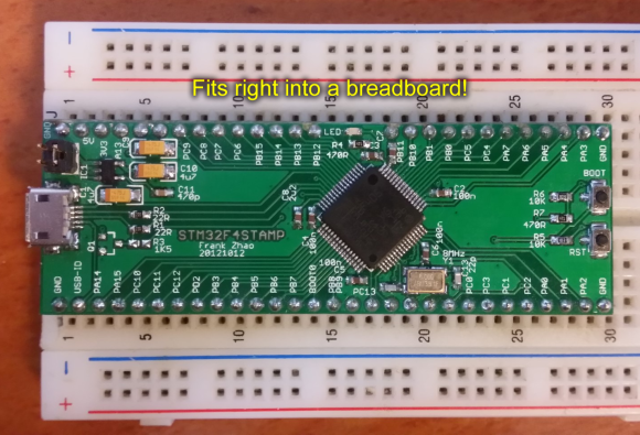
Umm yeah… this is more like it. The STM32F4Stamp is a project which [Frank Zhao] put together to make his ARM prototyping process more like is was back when everything came in a DIP format. As you can see, it’s just narrow enough to leave one row open on the breadboard for jumper wires.
Don’t get us wrong, we do really like STM’s own Discovery Boards for the hardware they deliver at a very low price. But the dual-row pin headers on the larger versions (all except the F0 variant) make it tricky to connect your peripherals. This is pushed to the point that a large percentage of hacks we’ve seen with the Discovery boards are actually just to make connecting external hardware easier.
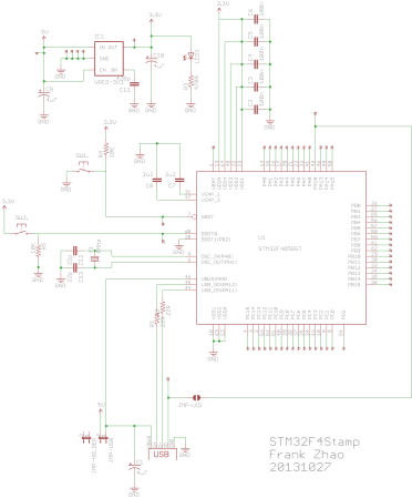
You may be thinking that there’s a lot missing from this board, but we disagree. Obviously there’s still a USB port which can be used to power the board via a 3.3V regulator. But since the STM32 chips have a built-in bootloader the USB connection can also be used to flash firmware to the processor. Nice! It’s open hardware if you want roll your own. For your convenience we’ve embedded the schematic after the break, along with [Frank’s] demo video.
http://www.youtube.com/watch?v=dJDpkEFYyiw
 [via Dangerous Prototypes]


Nice…. I want one
..except there is only one row left for wires.
No, it is 4 rows, if you first build the circuit, and then plug this thing in
No, one row.
Where are you supposed to put the components and sensors?
There are actually breadboard manufacturers out there that do 6 (SIX) whole pins per row, there really doesn’t seem to be much of a practical reason for doing them in 5s.
There are also breadboards with wider center spaces. I have one that fits old microprocessors like the Z80, 6502, etc.
That board could be made a little smaller so you have more than 1 row of pins on each side. It looks like it’d be pretty easy to have 2 on each side.
Not sure what you mean as breadboards have rows of sockets shored for hookup?
*shorted*
He means free space on the breadboard rather than pins on the board.
Gotcha, thanks
Not even a real need for making the board much smaller, just use https://www.sparkfun.com/products/9015 < right angle header pins on both sides of the board and then have the PCB sticking straight up in the middle of the breadboard.
Lots of great examples of what the stm32f4 can do are up on the subreddit: http://www.reddit.com/r/stm32f4/
The pins on the discovery F4 stick up, as well as down, so you can use standard machine pin wires to plug in the top and run them to the breadboard. Just buy a buttload of them from dealextreme for a couple bucks.
You only get 5 pins per column on a breadboard so any board you plug in is going to be too big.
So if I unscrew my breadboard from it’s base and then saw it in half along the centre line and then spread the halves apart so the module can plug into the inner pins of the breadboard THEN this module is “breadboard friendly” !!! Hmmmm
Just use two breadboards. Simple.
Mind = Blown http://pepijndevos.nl/images/mind-blown.gif
ST still doesn’t get it. Sure their hardware is decent, but the software is terrible. The compiler is crippled, and everything is windows only. The USB interface isn’t even HID, so you’re stuck unless you want to write your own drivers.
Use make, arm-none-eabi-gcc and openocd 0.7.0 (or newer).
OpenOCD works just fine with the STM32 discovery boards and you can build your own GCC toolchain or download a prebuilt one. I’m sure ST “get it” just fine.. They support platforms that all the guys that write code for manufacturers that their order parts in 10,000+ volume use and don’t worry too much about a few people that order in single units and run “weird” platforms.
You couldn’t be more WRONG if you tried!
1. Their software works just fine
2. ARM gcc compiler is not crippled at all
3. I can compile STM32 programs on OSX Linux or Windows without difficulty
4. STM32F4’s USB interface driver has both host and device modes, it can either be a HID or connect to a HID, no problems
One can only wonder about your deliberate misinformation and what axes you grind
As an alternative there is libmaple http://leaflabs.com/docs/libmaple.html, initially made for STM32F1 only, but ports exist for the F2, F4 and F3. It comes with a simple API and a nice unix toolchain.
Well, the ST-Link is supported well in OpenOCD, arm-gcc works great (espeically with -Os), and they publish interface guides for all their bootloaders.
Olimex did that lately with their olinuxino nano. Not only it’s breadbordable and arm based, but it basically runs linux. I bought a couple with no specific project in mind just because having a linux machine on your breadboard is sexy.
https://www.olimex.com/Products/OLinuXino/iMX233/iMX233-OLinuXino-NANO/open-source-hardware
please add “arm” to the tags :)
mbed has been doing this for years. (http://mbed.org/platforms/mbed-LPC1768/)
yawn, wake me up when mbed has floating point
Ask and ye shall receive. http://mbed.org/platforms/EA-LPC4088/ (Cortex M4 with FPU)
Made one like that last year, doesn’t expose all the pins, BUT it fits into a ATMEGA644 DIT socket footprint. I called it the “Brain Transplant” as it was made to replace a mega644.
https://plus.google.com/111387094029238541867/posts/CMJRSUj4vam
Yikes, I really hate to break it to everyone, but this already exists. The Cerb40 has been around for over a year and is on its second revision, which is excellent. It is a DIP40 format (I believe), fits easily in a breadboard, and uses the same STM32F405 processor. It comes with a .NET MF build, but can easily be flashed with anything else. And it’s cheap, just under $30. I have used them and they work great.
See it here: https://www.ghielectronics.com/catalog/product/450
Yes, the Cerb40 is quite excellent. My only complaint: it doesn’t break out 4 of the Analog Inputs. Other than that, quite swift, quite small (yes, DIP40) and quite cheap. Lots of bang for the buck.