

In case you weren’t aware, having a 3D printer is nothing like owning a real-life Star Trek replicator. For one, replicators are usually found on Federation starships and not hype trains. Secondly, the details of how replicated objects are designed in the 24th century is an issue completely left unexplored by TNG, and DS9, and only a minor plot point in a few Voyager episodes. Of the most likely possibilities, though, it appears replicated objects are either initially created by ‘scanning’ them with a teleporter, or commanding the ship’s computer to conjure something out of the hologrid.
No, with your own 3D printer, if you want a unique object you actually have to design it yourself. Without a holodeck. Using your hands to move a mouse and keyboard. Savages.
This series of ‘Making a Thing’ tutorials aims to fix that. With this post, we’re taking a look at Blender, an amazing 3D modeling and animation package.
Because we still haven’t figured out the best way to combine multiple blog posts together as a single resource − we’re working on that, though − here’s the links to the previous “Making a Thing” posts:
This list is sure to grow thanks to your suggestions on what 3D modeling software to feature, but for now let’s make a thing in Blender.
Our Thing
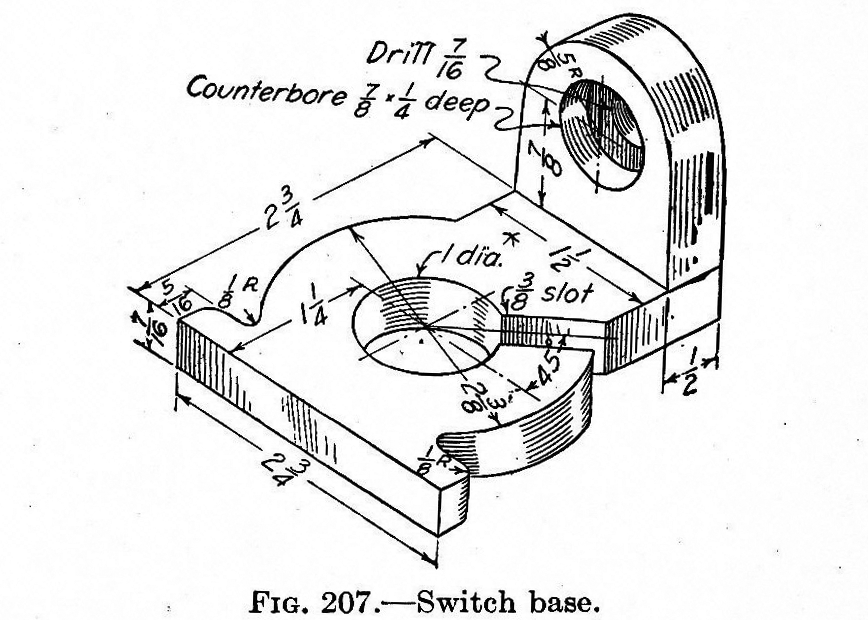
To the right is the part we’ll be designing in Blender. Just like the OpenSCAD and AutoCAD tutorials, we’re using the same object, a weird switch base thing taken from a 90-year-old book on drafting. You can click to embiggen that.
A Word About Blender
Blender is designed as a 3D animation suite. You know the old mid-90s Pixar short films? You can make those with Blender easily. Using Blender to design a small object to send to a 3D printer is like using a bulldozer to build a sand castle. You can do it, but it’s overkill.
Ideally, Blender should be used for objects that aren’t mechanical in nature. If you’re designing a gearbox for an RC car, don’t use Blender. If you’re making a replica of the Antikythera mechanism, don’t use Blender. If, however, you’re designing something more sculptural – a Pietà, for instance – Blender is a great tool.
Despite Blender being complete overkill for this simple part, and the fact Blender isn’t well suited for designing mechanical parts anyway, a lot of people asked for a Blender tutorial. Who am I to argue with the commentors on Hackaday?
Starting Up
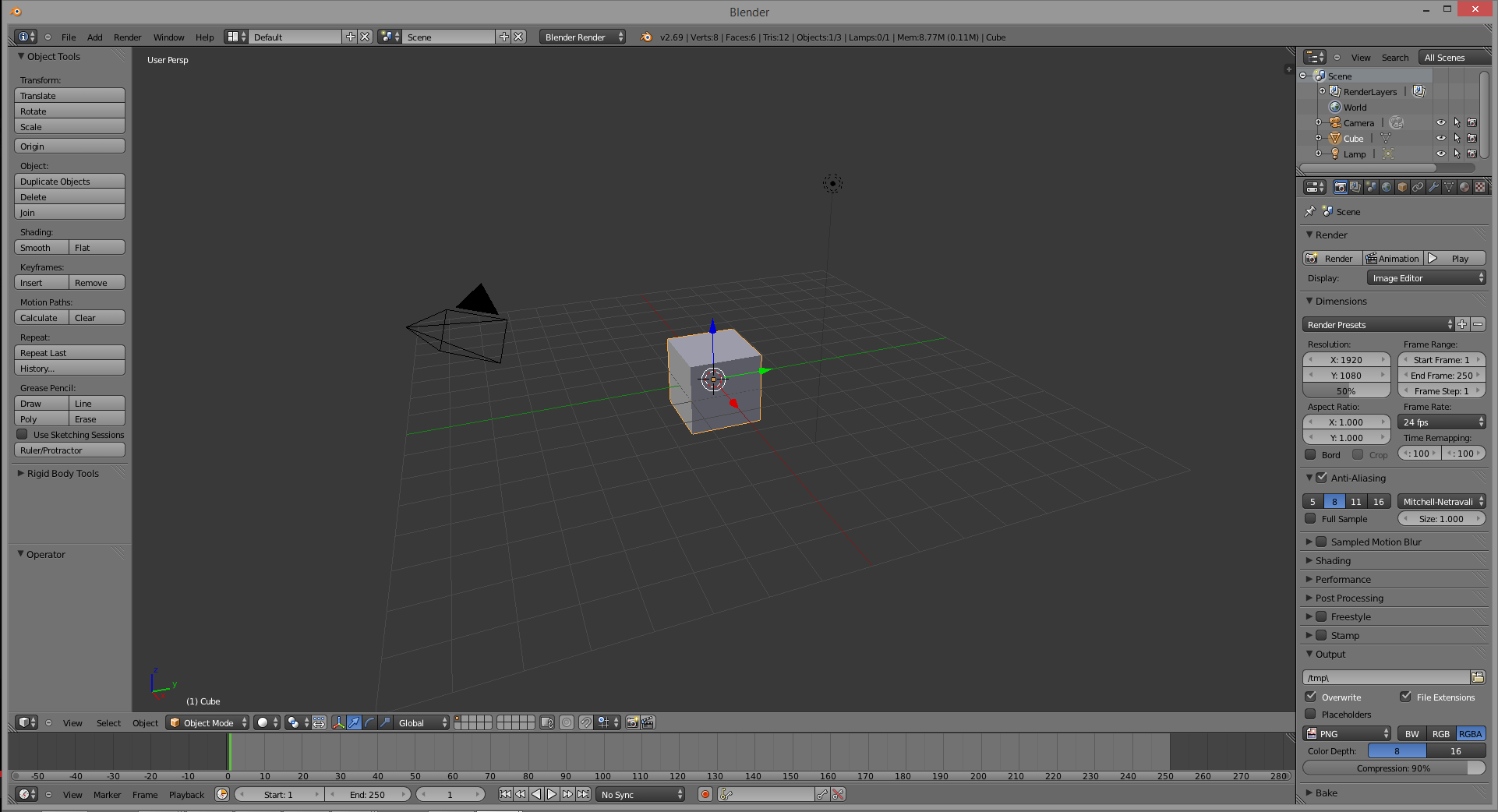
Installing Blender is left as an exercise to the reader. Do that here. When you first start Blender you’ll see the following screen that includes a cube, a camera (the pyramid-looking thing), and lamp. This is the default starting screen and we don’t need any of these objects. On your right hand toolbar, go to your Scene tab (at the top of the toolbar), right-click the cube, camera, and lamp, and delete them.
Meshes
Now that we have a blank canvas, we can start designing our part. Since this part of this tutorial is already halfway done, we’re only going to design the ‘washer’ part of our thing – the circle with a 3/8″ slot.
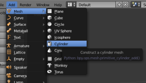
Instead of editing solids like OpenSCAD and AutoCAD, Blender does things entirely differently. It uses meshes, or collections of vertices (points in 3D space), edges (lines between two vertices), and faces (polygons made of edges) to define an object. We can start building our thing by making a cylinder mesh. From the top menu bar, select Add -> Mesh -> Cylinder and left click. A cylinder will appear at coordinates 0,0,0 in your scene.
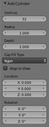
After you’ve done this, you’ll see an ‘Add Cylinder’ window on your left hand toolbar. This window allows you to edit the number of vertices, the radius, and the depth of the cylinder. Now is a good of a time as any to start editing our part, so make the radius of the cylinder 1.1875 (one half of the 2 3/8″ diameter of our part), and the depth 0.4375.
By the way, yes, I am regretting using a part from a 100-year-old drafting textbook right about now.
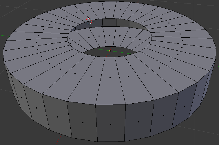
Here’s what we end up with:
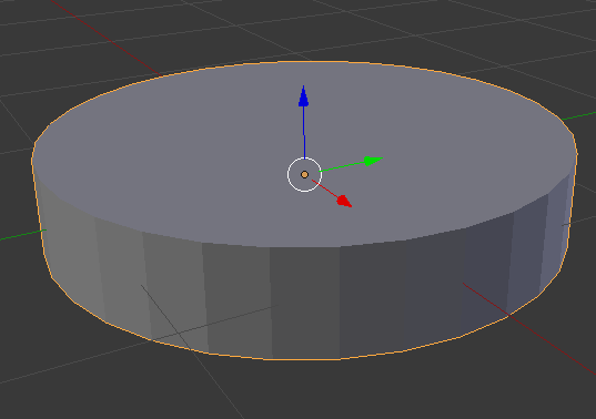
That’s making a very primitive object in Blender. To make anything useful, though, we need to go into edit mode.
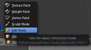
At the bottom of your Blender window, you’ll find a menu that will change how you can interact with Blender. Right now we’re in Object mode, which allows for the creation of meshes, surfaces, cameras, and lamps. To edit our object we need to be in…. Edit mode. Click on the little pull-down menu and change over. Doing this allows us to edit all the vertices, edges, and faces of our object. Here’s the cylinder we just created with all these selected:
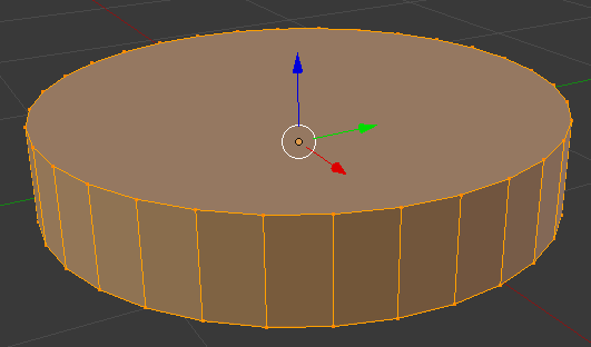
Hit the ‘A’ key on your keyboard to deselect everything. Now the cylinder is gray.
Now we need to put a hole in this part of our thing. If we were modeling with solids, we would simply create another cylinder, smaller than the one we have now, and subtract it from our current model. We’re not working with solids, though; we need to create the faces of our objects without Boolean operations.
To create the hole in this part of our thing, select the top face of the cylinder and with the ALT+F keyboard combo, select inset faces with the tool tip pop up thingy. Insetting a face allows us to create a new top and bottom for this cylinder that will correspond to the exact sized hole we need.
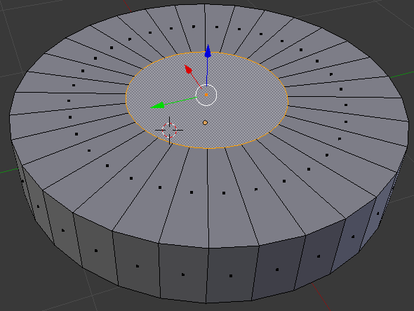
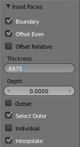
When you enable the Inset Faces command, the size of the hole you’re creating is dependant on how far you move your mouse; not great for something we’re creating from precise measurements. On the left hand toolbar, though, you can enter the thickness we want.
Here’s how the math goes, if you’re wondering. The ‘cylinder’ of our part is 2 3/8″ in diameter, and we want a 1″ diameter hole in the middle. Subtract 1 inch from 2.375 and you get 1.375. Since the thickness of this face is in reality a radius, divide 1.375 by two and you’ll get the number we want. I truly hate decimal inches.
After deleting the top part of our hole, flip the part over in Blender and do the same thing to the other circular face of our part. You’ll end up with something like this:
Now all we need to do is join up the top and bottom faces.
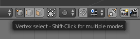 On the toolbar where you selected Edit Mode, you’ll see a set of three buttons. One is a cube with a vertex highlighted, one is a cube with an edge selected, and the other is a cube with a face selected. Any ideas what these buttons do?
Instead of individually selecting each of these edges on the inside of our part and creating 36 individual faces, we’re going to do something much simpler. Holding down the ALT key, select one of the inside edges with the right mouse button. This enables edge loop selection. Now, on the mesh tools toolbar (left side), hit Extrude and press the ‘Z’ key on your keyboard to lock your mouse input to one axis of movement.
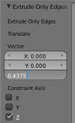
Again on the right toolbar, you’ll see a trio of boxes labeled ‘Vector’. This is how far Blender will extrude our…. extrusion in the X, Y, and Z axis. We want to extrude this edge 7/16″ (or 0.4375 decimal inches in the negative Z direction. That’s easy enough.
Here’s what we end up with when that’s done. Yes, it took me one thousand words to describe how to create a washer in Blender.
So what did you just learn?
As far as the creation of our ‘thing’ in Blender, we didn’t get very far. There’s still flanges and holes and round overs to do, but this is only part one of this Blender tutorial. Hopefully this served as a good introduction to Blender’s meshes and editing those mesh’s faces and edges.
See you here again next week!


One time i designed a part in blender… then i realized that the tool is about as user friendly as herpes. It can work if you know the ~1,000,000 hot keys and really only want it to look right. I concur that this is like building a sand castle with a bulldozer, the castle will not be the right size or perfect shape but there will be sand when you are done.
Blender’s UI isn’t actually bad. You just need to familiarize yourself with the logic behind tiling window managers, like i3 WM. And, if you’ve ever used a crashy, convoluted slice of shit like Maya, Blender is a breath of fresh air.
For mechanical CAD it is not the right tool, I am not arguing that it isn’t a good tool, but if i am designing a part for print, it is not my friend.
It’s actually pretty good for prints. You’re working directly with mesh geometry, so exporting an STL is a pretty trivial matter. It comes with tools to check your geometry for errors and features that might be problematic for printers, clean it up, and rescale it for printing. Beats mucking around in MeshLab, in my opinion.
That said, we are in agreement that Blender isn’t good at CAD work. But, it’s not a CAD program. I personally don’t get why anyone would even consider Blender for precise mechanical parts, but there seems to be a fair number of people who do.
Complete agreement, i do prefer skupltris for sculpting, but it is not the same as blender, it is just nicer for making faces and what not, Blender feels like it handles the nodes too harshly, skulptris feels more like clay.
The fact that people don’t take the time to learn how to do exact work in Blender is a shame. It can do it, unfortunately, most users are doing sculpting or animation. So those who wish to do exacting work have to wade through the docs to learn how it’s done. (Or search out those who are doing mechanical and architectural work.) I make mechanical assemblies and parts that mate all the time. Don’t get me wrong there is a steep learning curve, but it’s worth the climb. As for the hotkeys, there’s plenty of em…but, after you learn the few you need for day to day stuff it’s actually faster than finding commands with a mouse in that tab, under that tree, in that menu, behind that tab. But, as usual…YMMV.
Keep in mind, Blender is a mesh editor. It’s very competent at organic, sculptural forms. It’s much less competent at making parts with precise dimensions. It can be done, to be sure, but it’s an exercise in frustration.
It pays to know how to manipulate objects and be precise in any program, but that’s really not what Blender’s about. You can’t blame people for not wanting to use a masonry hammer to drive nails.
Blender is nice because it is free, but I think that’s the only nice thing about it. :( 10-15 years ago I did a lot of CAD work for things that would today, very likely, be 3D printed in small runs. Back then, we machined them from PET or Nylon. There are a lot of nice programs now, but my favorite is still FormZ. For parts that need both biological look and mechanical precision, it has an extensive and precise spline/surface modeling toolset. Frankly, I think it is still better than SolidWorks in that respect. The only other respect it is better is price, but it’s still not free. :(
I have used skupltris, it is wonderful for making organic 3d models (part of the zbrush family) but it is terrible for making printed models on its own. Skupltris is free, and does a better job of “sculpting” then the blender environment does.
Camerin: What software would you recommend then, for creating precise non-organic 3d models (for 3d printing)
I dont know FormZ but Blender has: Meta-Meshes, Multy-resolution-meshs, Sculptmode, and multiple types of Surfaces.
Blender is absolute bliss once you get past the hotkey learning curve. I’ve used it to design all kinds of things including boat hulls. The new freestyle renderer in the late 2.6x versions is excellent for doing line art illustrations of mechanical items. I use Blender for mechanical stuff more than for any other purpose.
I did lots of organics, scenes, rendering nodes, animation, and I learned at least a taste of it all. Right now I’m stuck with this cheap CAD/CAM program, it’s giving me grief, and If I can control things dimensionally for some mechanical parts then I want to use Blender. CamBam works but I keep remembering all the nice things Blender could do that would be murder to attempt with CamBam :-) http://img10.imageshack.us/img10/1905/workingwith.png (old work when I was 18, I just got burnt out, and went to something else that involves 3d but not “art”. It’s all done in Blender minus some of the splash and a bit of the light halo)
I started using Blender in the earlier 2.4X series and even used it during the 2.5 alpha. I love it, I don’t use it a lot now, and it’s used for boring tasks but I love it since I know how to use most of it so if I want to do something it’s effortless for the most part The newer modeling tools are a bit new to me, but that’s neat you can actually know how big the extruded hole is nowadays. I used to use YafAray for the rendering engine but it appears Cycles finally won out over most.
Lame question here, in the past two years has Blender finally gotten enough things polished up so I can make mechanical things? It seemed to lack the polygon modeling tools that would allow you to do stuff like that. Keeping in mind I’ve stayed aay from the new this that and the other since 2.5 beta since I went from using it for fun to mundane chores…..
(Mod please delete the cluttering of my post, I”m still used to forums.. sorry about the mess)
Eh, they’re fine.
I take issue with the suggestion that Blender makes making Pixar-esque short films easy. I’d rather argue that Blender makes it possible. Animation is not an easy task, no matter what tools you have on hand. Even with skill and talent, it’s a lot of work.
I mean, sure, it’s a minor point, but I’d hate to see yet more people think they can make “Luxo Jr.” or “For the Birds” just by downloading Blender.
Great article, I now understand the principals of modelling in Blender. I’ve been using Solidworks, FreeCAD and OpenSCAD for a few years, scared to learn Blender, but i will now. Thanks
Blender is free. It’s much better than any other free program to edit 3d. I hoped that design spark would be good enough, but for me it’s better to learn blender, than play with program which is similar to Inventor, but only by it looks.
Also blender is not too much worse to make things, than standard Autocad. (Many people won’t agree here, but as a student I tried both… standard Autocad is not suited to complex 3D) which I can’t afford. Aside that I would have to install windows on my poor laptop, he would hate me for that.
Why not to use booleans? For me, as I was printing stuff for last week three things solved my problems: double check, non-manifold check and lastly general check from 3D printering add on. Sure thing that learning blender I just licked it a little, and have my precious list of 10 most used keys but it works.
Also at the very beginning shouldn’t there be units set up? I did it first and truly don’t know if it would work without it :)
Lastly on this topic blender is open. I thought hackers like open things the most ;]
Ps. I would never do that like that, even though I like math – too much beating around bushes ^^”
I’ve read a lot about blender and did a simple tutorial with it. In the past I’ve used Autocad and sketchup.
Why does everyone say Blender can not make precise mechanical objects? If you printed an engine made in blender would each piston have different dimensions? Is a 1x1x1 inch cube made in Blender not 1 inch? Are the edges not at 90 degree angles?
I don’t understand why Blender is bad for mechanical objects…
For starters, Blender doesn’t work with real units. You can certainly export your model something that does, but heavens help you if you need to mix different unit systems for whatever reason.
Second, its support for NURBS isn’t very robust, so there are pretty much no true rounded edges in that program — a sphere in Blender looks more like a cut diamond. Granted, when you export a solid model to something printable, the same thing happens, but the end result is more precise and thus much truer to your design intent, and you don’t have to worry those details when you build the object in a proper CAD program.
Third, Blender’s models are not guaranteed to be watertight, and there are a lot of extra productivity-killing steps you need to take to make useful objects. Unlike a solid modeler, where you lay down features and set dimensions, with Blender, you manipulate vertices, edges, and faces. What this means is that: A) you can have holes in your model which you need to look out for and repair and B) if you want to do anything more than simple extrusions and transformations, you need to screw around with deleting and adding the aforementioned vertices, edges, and faces.
Fourth, Blender does not offer any notable drafting tools, and it’s not very good for building part assemblies or manipulating features after the fact.
Basically, in a nutshell, although you can make mechanical parts with Blender, it’s really not a good tool for the job. It has a lot of features not really useful for CAD work, and it’s got precious few features for making precise parts.
An analogy: Say you want to cut steel pipes. You could use a chisel as a makeshift trowel, dig a hole in the ground to hold a pipe, using a coping saw to cut it, and then take off the burrs with 600 grit sandpaper. But, let’s not pretend that’s a good way to do it. You really ought to have a vise, a hacksaw, and a file. But, if you want to do decorative woodwork, the vise, hacksaw, and file won’t do you much good — you’ll need the chisel, the coping saw, and the sandpaper.
It’s all about picking the right tool for the job.
Taking 3D printer to make stuff, not buying stuff if the same as your analogy – it’s hard way. (Well being maker means doing things around because we want and it’s possible ^^)
First: I don’t know why would you want to mix dimensions. I didn’t see technical drawing like that and don’t know what kind of situation would make me to do it like that.
Second: You can just add more resolution (vertices) to your model. I really wonder if in cad file circles are saved parametrically if it’s that great.
Third: You never can have hole in your model, its just easier when you work with bricks. But try to model car body like you say – like a brick. Even in cad programs it’s not always about bricks.
Fourth: I have to agree – blender really lacks, if you want to work like in inventor. It’s totally different. You have to have serious skills if you want to model something more complex, and you don’t have MES here so you should calculate something sometimes.
It’s all about money. If people had x thousandths bucks just to throw away they would buy much better printer (why should bother with this cheap stuff?) And would buy autodesk inventor + 3D manipulator (my love) just to work parametrically. (Not this lackey standard autocad)
You can buy 40W laser cnc to cut your morning bread, and you can have knife. Knife might be less accurate, may need more work to cut, and your bread won’t be heated from it even a bit. Yet you choose knife, why?
It seems I’m blender lover – I’m not. If anybody told me in firm “We make mechanical stuff here in blender” I would think they are nuts. How ever if somebody told me “I bought program for tenths thousands bucks to model raspi cover” I would think worse…
A 3D Printer is an extremely versatile tool, and it enables making parts that would otherwise be difficult or costly to make. That even goes for FDM, which has some considerable drawbacks compared to other 3D printing methods. People got by without digital computers, but computers are in nearly everyone’s home and most people’s pockets these days. No reasonable person would get a 3D printer just to
First off, there are a number of reasons why someone might want to mix dimensions. Let’s say you need to build an adapter between two assemblies done in different units. It happens more than you think.
Second, adding more edges is not the same as having a true circle. You will never have true curves in a mesh modeler. Modern solid modelers work with curves and surfaces: it’s a whole different approach. How about you look up NURBS, start from there.
As for the third note, I don’t think you understand what I’m suggesting. Like, at all. I don’t even know WTF you mean by bricks.
In a solid modeler, if you want to make a counter-sunk through-hole, you add an extrude-cut feature that goes through the model, an extrude-cut feature that goes as deep as you need the countersink, with an appropriate draft angle, and you’re done.
With Blender, to make that same countersunk hole, you need to need to use the Inset Faces tool, extrude the new face down as deep as your countersink goes, bring in the deeper edge to the same diameter as your through-hole and hope you got the angle correct (and chances are, you only got it close, not exact), delete your inset face, make and delete another inset face as wide as your through-hole, bridge the two gaps, and then check the model to make sure there are no missing faces. The model stays watertight throughout it all.
If you neglect that last part in Blender, I repeat, IF YOU NEGLECT THAT LAST PART, you can very well end up working with geometry thats not valid for generating g-code, and as your model grows in complexity, fixing that problem may be a headache unto itself.
And if you want to make a thread in that hole, for whatever reason, forget about it. You’ll spend hours in Blender making a half-assed thread that won’t work quite right and will likely lead to problems with your model geometry. Blender artists just add a normal map to simulate a thread, but that won’t cut it for CAD. In a solid modeler, you’ll often find a thread feature — and lacking one, you can always just make a helix and sweep the thread along it.
Moreover, with most decent solid modeling packages, you can generate your geometry according to equations. Do you need to ensure one dimension is larger than another according to some exponential curve? Can’t do that in Blender. You can’t even go back and easily change your dimensions for that matter.
And sure, with most solid modelers, you can break down a model into surfaces. But if you do that, unlike a mesh modeler, you won’t be off on your merry way, oblivious to what you just did. If you fail to knit your surfaces into a watertight solid object, you cannot use solid modeling tools on that item, and if your surfaces are not manifold, you cannot knit them. So there’s no getting away with incomplete geometry in a solid modeler.
Lastly, the programs you ought to be measuring Blender against are Maya, 3DS Max, Cinema 4D, and modo. Inventor is in a whole different category of software.
And what’s this about dropping thousands of dollars just to make simple models? You have not done your due diligence. Between FreeCAD and CadQuery, there are some pretty competent solid modeling tools that are free-as-in-beer and free-as-in-speech. There’s also OpenSCAD and BRL-CAD, which are also quite powerful, though they’re limited to constructive geometry rather than curves and surfaces.
Now, if I come across as a Blender hater, I’m not. I love Blender and use it from time to time. But, if it’s not the right tool for the job, let’s not pretend that it is.
I must correct an accidental deletion.
“No reasonable person would get a 3D printer just to” make simple tasks more difficult. 3D printers enable people who lack the manual skill to make objects, or who have imaginations that the tools and materials available to them otherwise can’t realize.
And another correction. Somehow “The model stays watertight throughout it all.” got transposed to the wrong paragraph.
It should have been:
“In a solid modeler, if you want to make a counter-sunk through-hole, you add an extrude-cut feature that goes through the model, an extrude-cut feature that goes as deep as you need the countersink, with an appropriate draft angle, and you’re done. The model stays watertight throughout it all.
With Blender, to make that same countersunk hole, you need to need to use the Inset Faces tool, extrude the new face down as deep as your countersink goes, bring in the deeper edge to the same diameter as your through-hole and hope you got the angle correct (and chances are, you only got it close, not exact), delete your inset face, make and delete another inset face as wide as your through-hole, bridge the two gaps, and then check the model to make sure there are no missing faces.”
Decent people have drill home, so why not to have 3D printer. It’s still costly, but not that much.
I’ve never met this problem before – so for me its quite new. But someone wrote – you can just scale it – if you have to. How is it done in free cads?
So modern cad program has circle saved parametrically?
Solid = brick, my bad for that “shortcut”. Now you know it, so you can think about it again.
Thread – if my printer could print anything with threads I would bother with them.
Cutting everything else short. I wrote about inventor because I really miss working with parametrically described models where one change in dimensions moves everything. In comparison to it free programs are not even toys. When I was doing my recognition in free cad’s none of them could easily change size of object, never mind making threads – so why not to use this overkilling blender to do some stuff?
I don’t understand what drills have to do with this.
I don’t see what you mean by scaling. Mixing units is mixing units. Let’s say you need to make an adapter plate for a 1/4″ tripod screw to hold a camera and some M5 screws to mate with T-nuts. One’s imperial, one’s metric. There’s no scaling, there’s just a need to accommodate different units.
Yes, proper CAD software does have true circles. It has for decades now. They’re not necessarily parametric — that depends on the package you’re using.
You’re still not making sense about bricks.
As for threads, coarse ones can be printed even with a cheap printer, something comparable to the ones you might find on a laundry detergent bottle. Fine ones, you’d probably want to tap them for precision’s sake, even if you’ve got a $500K printer that can print them.
And as for FreeCAD, you need to constrain your sketches first. If your model is not fully defined, bad things happen when you try and change dimensions. Without a constraint, the software goes, “Okay, this curve isn’t set in stone, which means we can alter them to accommodate this new change.” It’s really very similar to any serious feature-based modeler like SolidWorks or NX. If you’re mindful of that, changing individual dimensions is straightforward and keeps everything nice and neat.
Scaling entire objects, however, hasn’t yet been implemented. You really ought to be building your model according to the correct dimensions to begin with anyway. But, if you’re so inclined, there is a Python console included, and it works with NumPy, so you could probably whip out a script to scale things that way.
Blender is not even overkill. It’s the wrong tool. It’s severe underkill with a mountain of features not relevant to CAD work.
Just a few little things:
“First off, there are a number of reasons why someone might want to mix dimensions. Let’s say you need to build an adapter between two assemblies done in different units.” Property-Panel=>Scene=>Units Do whatever you want to do in one unit using the one unit type, then whenever you need to change, set the other unit-type on.
“How about you look up NURBS, start from there.” ? Blender has NURBS.
” to make that same countersunk hole, you need to need to use the Inset Faces tool, extrude…” Nope, Blender has Boolean operators.
“hope you got the angle correct (and chances are, you only got it close, not exact)” Blender allows you to clip on points, edges and faces as well as on angles and 3Dcoordinates, so you could make a example-edge and get it precise. you could also use a cone with defined angle, you could use SPIN, if you really want to use inset, type in the depth of your final plane, and what angle are you even talking of?
“delete your inset face, make and delete another inset face as wide as your through-hole, bridge the two gaps, and then check the model to make sure there are no missing faces” How about: extrude the inset face, snap it to the other face, kill both faces, select the vertices of the recently killed faces and then use SPACEBAR=>’Bridge Edge Loops’ (no chance of open faces, no struggle with the size of the second inset face 2-3 steps less)
” In a solid modeler, you’ll often find a thread feature — and lacking one, you can always just make a helix and sweep the thread along it.” Blender has a BOLTFACTORY-addon, use it (if your not capable of choosing NUT use BOLT and then use boolean on it), done. or you could just make a V and use SREW. you could do that with at least 2 different ways using curves. OVERKILL: using python, it were about 10 lines.
“Do you need to ensure one dimension is larger than another according to some exponential curve? Can’t do that in Blender.” would you kindly be more precise? But if I got you right,… you could do that via Python in less than 10 lines.
“You can’t even go back and easily change your dimensions for that matter.” 1. Why not? 2. use the Mesh-Deform-Modifier. (Of course you would not do that if you need 10 digits accuracy after the decimal point. But if you need that you’ll either have a expencive CAD at hand, or be capable of creating some Python code.)
I’d never dare to say you would hate Blender, BUT I dare to ask you how long/much you have used it, since you seem to miss knowledge about on a lot of it. I’d say for high accuracy use autoCad but for you usual 3D-prints just use Blender.
Once again, it’s about figuring out how to do it. Making manifold objects is not that big a deal once you learn how. Doing assemblies is the same.
Is Blender going to steal business from Mechanical Desktop? No. But blender doesn’t cost k$.
You can figure out how to do just about anything using just about anything. You could probably solder electronics with an iron rod heating up in a blacksmith’s forge. With practice you could probably even get really good at it. But really, that’s a bit of a ridiculous proposition nevertheless.
Blender isn’t the only free program out there, by the way, as in speech or as in beer. Have a look at FreeCAD. It’s still a young project, rough around its edges, but it’s already quite capable. It has all the basics down pat, at any rate.
Also, mixed dimensions is simply scaling. I mix metric and imperial. I import a lot of dxf. Some in metric, some imperial, some scaled by some wonky implementation of dxf export. I also use scanned images,scaled appropriatly, to build models that fit around the scanned object.
And if you wish to make a part from scratch? If you’ve only got a list of dimensions, without a DXF to work from or even an image for reference, Blender doesn’t cut it, not without other tools at any rate.
Many complain of Blender not being suited for mechanical models. I would like to hear from someone who uses blender to 3D print. I haven’t seen very many complex “mechanical models” being printed whatever software is used. Pi Boxes/Crates Yoda Vader Assorted female statuary etc.
Seems to me as long as the user is happy with what thier using and the results are good.
I use it to do 3d printing of mechanical parts all the time. Currently working on a complete assembly of a desktop cnc in blender. In many cases for complex profiles or where geometry already exists in dxf I’ll import the dxf to start a part.
there is a plug in/script for blender called blender CAD that adds a lot useful features for mechanical modeling, in addition you can set the size of units used for measurement ie metric or imperial and you can type simple equations ie 5 + (1/3)
this is not required. i can just install blender (even the older version that debian still ships) and i can type 1 + 1/3 on the size and it simply works. also blender has boolean operations. i don’t know why the genious on this article was going to edit mode.
this article is a joke. …and this series started so well.
I have used Blender for 3d modeling a bit and although the interface has a rather steep learning curve compared to most 3D modeling applications, it is incredibly robust, and with enough time spent, quite fluid in workflow, which is especially impressive due to it’s incredibly low price. I have not, however, used it to make anything with my 3D printer, in fact, I’d never even thought about it. I have always thought that it was exclusively a mesh modeling program, not for solids. Thanks for the info! I will keep up with this one!
Technically, using a mouse and keyboard is “quaint”. :)
I use Blender to create stuff to print – have never used anything else. Steep learning curve indeed but very fast once you get over the hump. Recent versions have good tools for mesh analysis reporting on non-manifold meshes, overhangs etc. http://wiki.blender.org/index.php/Extensions:2.6/Py/Scripts/Modeling/PrintToolbox
It does do nurbs, it does do real world units, it does do precision (press ‘n’ for numerical input). The above tutorial would be easier using boolean modifiers.
I certainly haven’t hit the limits of what it can’t do. Works for me. Haters need to update and try again. For sure, it’s no auto-cad, but is much cheaper.
Merely having the feature available is not the same as having it be good.
Blender’s support for NURBS is pretty shabby. Try Rhino, and then we’ll talk NURBS. There’s sadly no free/libre open-source alternative to Rhino, but all the same, Blender is not it. Maybe it could happen if NURBS would be expanded so it would be an end in and of itself (not just a way to build up mesh models), and and if Blender would offer useful NURBS features like sweeps along multiple rails or lofts with curvature continuity between surfaces.
Blender’s real-world units are useful for modeling within a measurement system, not converting between them, and not mixing them without conversion. You can have multiple unit systems within different scenes, but not within the same scene. Switch the units for a scene, and all your measurements are destructively converted to the new system. If you make a hole that’s 1/4″ and switch to metric, Blender will treat that as 6.35 mm, not 1/4″. For simple models, it’s probably not important, but as your models increase in complexity, it can allow some really ugly errors to creep in, especially when you need to deal with tolerances.
Numerical input is a far cry from constraints or even proper dimensioning. You make a circle in Blender that’s, say, 3 units wide, and that’s it. You can’t go back after the fact to make it wider just by clicking it and changing a parameter. Granted, this is a limitation shared with just about every other mesh modeler out there, but it’s a pretty harsh limitation nevertheless.
Booleans are not so simple. Blender does it better than Maya, but as with any mesh editor, it doesn’t guarantee good, clean geometry — if you can, it’s better to just sculpt what it is you’re working on, rather than treating Blender like a constructive solid modeler. (For example, even a simple difference between two cylinders to make a simple wheel will generate a very messy zig-zag pattern across the ends of the cylinder — if you want to do more with either surface, you’ll have to delete that face and rework it by hand.)
Blender is an excellent program with a lot of really cool features, don’t get me wrong. It’s unique with its 3D printing tools. It’s a joy to use once you learn it. But, using Blender for mechanical models is like using a masonry hammer to frame a house. It can be done, but why?
I used Rhino only a bit, but where is the difference concerning NURBS ?
Marketing.
20 years ago rhino was the only one that did nurbs. and while it was lousy as cad, people in the boat industry lived by it.
today, they failed to inovate in absolutely everything, so their marketing just shouts NURBS! louder and louder.
Yeah… no.
Rhino is pretty robust, and it makes hammering out complex, flowing, organic forms pretty damn easy. Not to mention, there’s also Grasshopper for generative modeling. You’ll find more than just boat designers who swear by it. A lot of architects and product designers have it in their workflow as well.
*Ahem*
“Maybe it could happen if NURBS would be expanded so it would be an end in and of itself (not just a way to build up mesh models), and and if Blender would offer useful NURBS features like sweeps along multiple rails or lofts with curvature continuity between surfaces.” To give a couple of examples.
Perhaps Blender has expanded its NURBS capability over the past two years (haven’t bothered, since I do have Rhino handy), but at the time of writing that post, that was quite a pertinent comment.
IMHO you might want to do an example using Wings3D. It generates watertight meshes and is easy to make this kind of object. Also exports in stl to go straight to printer
Same done in 6 steps:
1. Press A, A, X, ENTER to delete all
2. Go to Property-Panel=>Scene=>Units to set your unit-type
3. Shift-A => Mesh => Cylinder, Cap-Fill = None, Radius = radius of the hole in the washer, Depth = thicknes of the washer
4. In Editmode press E, RMB to extrude without movement.
5. Press S, Shift-Z (to scale only in x and y) and type in the outer size.
6. Press S, Shift-Z, / on the numpad and type in your inner size, done.
Same done in 6 steps:
1. Press A, A, X, ENTER to delete all
2. add Plane (Shift-A => Mesh => Plane) at X=inner radius and go to top view(Numpad 7)
3. In Editmode: Alt-M => at Center to collapse to a single point, and E (outer radius – inner radius) to extrude
4. Press A, A, Alt-R to select both vertices and Spin (-360 degrees)
5. Press A, A, SPACEBAR=>’Remove Doubles’
6. Press E and type in the height, Done
Same done in 5 steps:
1. Press A, A, X, ENTER to delete all
2. add Cylinder (Shift-A => Mesh => Cylinder) R=inner radius, Depth > thicknes
3. add Cylinder (Shift-A => Mesh => Cylinder) R=outer radius, Depth = thicknes
4. Add modifier: Boolean, Difference, Object= first Cylinder and apply.
5. Kill first Cylinder, done.
Thank you! Not only is it a simple task and easy to do, but you can work with precise units, Imperial or Metric or otherwise. Just like any serious program, you need to learn the shortcuts. I work in Adobe programs all day and if you’re doing any serious work, both your hands need to know the hotkeys.
I do not understand what “tool tip popup thingy” is.
Sorry but I found this tutorial almost worthless.
You should not need to spend an hour googling “Blender tool tip popup thingy” – tutorials should be self-explanatory, not requiring the reader to already be an expert in the subject matter.
take a look at mechanical blender ;)
http://www.mechanicalblender.org
It’s a large project, but it has already some tools that could be really useful for this purpose.
I highly recommend also using the 3YOURMIND plugin for Blender (https://www.3yourmind.com/3d-print-add-on-blender)
It ensures that your model is actually 3D printable including doing basic formatting fixes to the file. The platform is totally free and analyzes your model specifically for the material you select.
Then just download the file and print! Easy.
I’m revisiting this post using :
https://makertales.gumroad.com/l/CADsketcher
parametric drawing plug-in for blender that’s coming along pretty nicely!
Arbitrary question for those of you that followed along with this, tutorial, did you taper the vertical drilled flange, or did you ignore the 5/8th r outer edge and go with the straight walled 3/4″ that you would get from the mating corner? always that question of how much you trust the draftsman ;P