Arcade Briefcase (the Briefcade)

20131109_134118

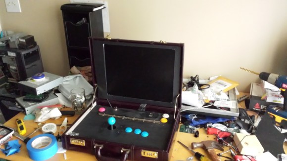
[Travis Reynolds] is part of an arcade club at work — the only problem? He’s the only one with an arcade machine, so they always end up at his place. So he decided to make his own portable, arcade briefcase to take to the office.

It all started with a quick trip to Goodwill where he found a beautiful maroon briefcase from the 80’s, for only $5! He then took apart a spare LCD monitor he had sitting around, and it worked incredibly well in his favor. He was able to reuse the LCD’s internal mounting brackets to secure it to the briefcase, and the video cables were just long enough to reach the Raspberry Pi.

The next problem he faced was the joystick height. He picked a Sanwa style joystick which is fairly small, but even that was too tall for the briefcase. So unfortunately, he needs to remove the ball of the joystick before closing the case. After testing out the proposed button layout, he cut a plywood mounting plate to hold everything in place. A bit of black spray paint later plus a power connector through the side of the case, and it’s complete!

He’s running Shea Silverman’s PiMame, which has an easy to use menu, quick setup, and great support. It’s an awesome project, and very well documented in case you’re itching to do something similar — I know we are!

Of course, if you have the space, a coffee table arcade machine is pretty sweet too…

[Thanks Brendan!]

Key Cutting With A CNC Mill

key2_zpsc260d079

Keys cost like what, $2 to copy at a locksmith? But where’s the fun in that? Here’s an easy way to cut your own keys using a CNC mill!

[Bolsterman] now “works” for a real estate company that rents out various properties. Whenever someone moves out, the locks need to be changed ASAP. They use Schlage locks, which can be re-keyed to any pin combination. New keys are typically cut with a punch or a key cutting machine — he actually had one years ago, but got rid of it. Not wanting to buy a new one for his new job at the real estate company, he decided to see how hard it would be to turn his small desktop CNC into his own personal key cutting machine.

All it took for [Bolsterman] to turn his mill into a key cutting machine was a 3/8th 90° countersink bit with the end ground to a flat approximately 0.055″ across (0.035″ is the width of a factory key, but a bit of leeway makes it easier to make the key). Then you simply zero the mill off of the shoulder of the key, and using the handy Schlage pin chart (included in the original link), cut the grooves!

To automate all of this, [Torrie Fischer] created a python script for generating the GCode  for keys based on [Bolsterman’s] technique — it’s hosted over at Noisebridge’s Wiki — check it out!

But if all that seems like too much effort, you could just print a new key instead…

PhotoTransistor Based Eye-Tracking

eyetrack

The applications of eye-tracking devices are endless, which is why we always get excited to see new techniques in measuring the absolute position of the human eye. Cornell students [Michael and John] took on an interesting approach for their final project and designed a phototransistor based eye-tracking system.

We can definitely see the potential of this project, but for their first prototype, the system relies on both eye-tracking and head movement to fully control a mouse pointer. An end-product design was in mind, so the system consists of both a pair of custom 3D printed glasses and a wireless receiver; thus avoiding the need to be tethered to the computer under control . The horizontal position of the mouse pointer is controlled via the infrared eye tracking mechanism, consisting of an Infrared LED positioned above the eye and two phototransistors located on each side of the eye. The measured analog data from the phototransistors determine the eye’s horizontal position. The vertical movement of the mouse pointer is controlled with the help of a 3-axis gyroscope mounted to the glasses. The effectiveness of a simple infrared LED/phototransistor to detect eye movement is impressive, because similar projects we’ve seen have been camera based. We understand how final project deadlines can be, so we hope [Michael and John] continue past the deadline with this one. It would be great to see if the absolute position (horizontal and vertical) of the eye can be tracked entirely with the phototransistor technique.

Continue reading “PhotoTransistor Based Eye-Tracking”

Build An Audio Spectrum Analyzer The Analog Way

bandpass

[Ryan] wanted a spectrum analyzer for his audio equipment. Rather than grab a micro, he did it the analog way. [Ryan] designed  a 10 band audio spectrum analyzer. This means that he needs 10 band-pass filters. As the name implies, a band-pass filter will only allow signals with frequency of a selected band to pass. Signals with frequency above or below the filter’s passband will be attenuated. The band-pass itself is constructed from a high pass and a low pass filter. [Ryan] used simple resistor capacitor (RC) filters to implement his design.

All those discrete components would quickly attenuate [Ryan’s] input signal, so each stage uses two op-amps. The first stage is a buffer for each band. The second op-amp, located after the band-pass filters, is configured as a non-inverting amplifier. These amplifiers boost the individual band signals before they leave the board. [Ryan] even added an “energy filler” mode. In normal mode, the analyzer’s output will exactly follow the input signal. In “energy filler” (AKA peak detect) mode, the output will display the signal peaks,  with a slow decay down to the input signal. The energy filler mode is created by using an n-channel FET to store charge in an electrolytic capacitor.

Have we mentioned that for 10 bands, all this circuitry had to be built 10 times? Not to mention input buffering circuitry. With all this done, [Ryan] still has to build the output portion of the analyzer: 160 blue LEDs and their associated drive circuitry. Going “all analog” may seem crazy in this day and age of high-speed micro controllers and FFTs, but the simple fact is that these circuits work, and work well. The only thing to fear is perf board solder shorts. We think debugging those is half the fun.

3D Printering: Making A Thing In Blender, Part I

printering

In case you weren’t aware, having a 3D printer is nothing like owning a real-life Star Trek replicator. For one, replicators are usually found on Federation starships and not hype trains. Secondly, the details of how replicated objects are designed in the 24th century is an issue completely left unexplored by TNG, and DS9, and only a minor plot point in a few Voyager episodes. Of the most likely possibilities, though, it appears replicated objects are either initially created by ‘scanning’ them with a teleporter, or commanding the ship’s computer to conjure something out of the hologrid.

No, with your own 3D printer, if you want a unique object you actually have to design it yourself. Without a holodeck. Using your hands to move a mouse and keyboard. Savages.

This series of ‘Making a Thing’ tutorials aims to fix that. With this post, we’re taking a look at Blender, an amazing 3D modeling and animation package.

Because we still haven’t figured out the best way to combine multiple blog posts together as a single resource − we’re working on that, though − here’s the links to the previous “Making a Thing” posts:

This list is sure to grow thanks to your suggestions on what 3D modeling software to feature, but for now let’s make a thing in Blender.

Continue reading “3D Printering: Making A Thing In Blender, Part I”

3D Acoustic Manipulation: Seemingly-Unreal Levitation Using Soundwaves

Wow. [Yoichi Ochiai], [Takayuki Hoshi] and [Jun Rekimoto] are researchers from the University of Tokyo and the Nagoya Institute of Technology, and they have just learned how to airbend.

Using a series of standing ultrasound waves, it is possible to suspend small particles at the sound pressure nodes. The acoustic axis of the ultrasound beam is parallel to gravity, which also allows the objects to be manipulated along the fixed axis by varying the phase or frequencies of the sound. By adding a second ultrasound beam perpendicular to the first it is possible to localize the pressure node, or focal point, and levitate small objects around a 2D plane.

In their demonstrations they float foam particles, a resistor, an LED, they show off the waves using a piece of dry ice, and even manage to float a small screw.

Sound like crazy talk? Just watch the video.

Continue reading “3D Acoustic Manipulation: Seemingly-Unreal Levitation Using Soundwaves”

Fire At The Geek Group

Geek Group

The Geek Group, an absurdly large and well stocked hackerspace in Grand Rapids, Michigan caught fire yesterday.

You may recall The Geek Group from their many over-the-top projects that include a quarter shinker, a 200,000 Watt Tesla coil, enough capacitors to kill a demi-god, and a giant robot that crushes TVs. From what TGG has shown on their website and their YouTube, they have an amazing space that could still be the home of quite a few amazing builds.

According to Geek Group head honcho [Chris], the fire was caused by an overheated electric motor. No one was at the space at the time, but the fire was hot enough to crack the exterior brick and melt porcelain insulators in their high voltage lab. To add insult to injury, this was only TGG’s second day of being open to the public.

The folks at The Geek Group are looking for volunteers for their cleanup, so if you’re around the Grand Rapids area and would like to pitch in, head on over around noon today.