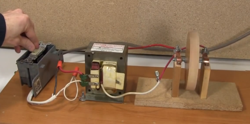
[RimstarOrg] has brought us an oldie but goodie this week. He’s built a ball bearing motor, a design which has been causing engineers and scientists to squabble for decades. [RimstarOrg] used a microwave oven transformer with a 70 turn primary coil and a single turn secondary coil to create a low voltage, high current AC power supply. Needless to say, there’s a real risk of fire or electrocution with a setup like this, so be careful if you try this one at home. [RimstarOrg] then built the motor itself. He de-greased two ball bearings then installed them on a metal shaft along with a wooden flywheel. The entire assembly was then mounted on a board so the wheel could spin freely. Two copper straps hold the bearings to the board. Finally, the transformer is wired into the copper straps. In this configuration, the current will flow through the outer race of one bearing, through the balls, and into the inner race. The current then passes down the axle and passes through the other bearing. There is very little resistance in this circuit, so it can only be powered on for a few seconds at a time before things start to melt down.
When the current is switched on with the flywheel stationary, nothing happens. If left long enough, the bearings will overheat. The real magic starts if you give the flywheel a spin just before turning on the current. As soon as power is applied, the flywheel starts to pick up speed. Power off, and things start to slow down. This happens both with the flywheel spinning clockwise and counterclockwise.
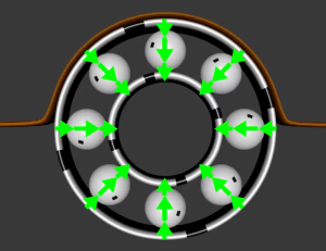
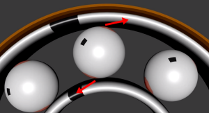
So what’s going on here? A motor with no magnets? Is this some type of perpetual motion machine? Alien technology? We can assure you that the effect is real, but the mechanism is still unproven. [RimstarOrg] explains one common explanation, which is the motor is operating as a heat engine rather than a standard electric motor. The metal ball bearings have relatively tiny contact points with their respective races. These small points create a large resistance, which causes uneven heating of the balls. The heated balls expand to ovals. If the entire ball bearing isn’t turning, the expansion force will simply lock the two races together. If the motor is turning when expansion starts, it serves to push the outer race along.
This isn’t the only explanation of the motor though. Several electromagnetic explanations for the motor’s movement have been presented over the years. The physics behind these explanations are rather complex. The complex math and integrals can be found in this 1977 paper (pdf link) by [H. Gruenberg]. A more recent example is in this 2011 paper (updated in July of 2013) (pdf link) by [Prof. Kirk T. McDonald] of Princeton University.
[RimstarOrg] isn’t the only hobbyist to tackle this problem – [Mike] has a page about ball bearing motors as well. He concluded on the thermal explanation. Even Wikipedia seems a bit confused on the subject. The only thing everyone does agree on is the fact that the ball bearing motor is too inefficient to have any practical purpose. We may be a bit naive here, but it would seem that some simple hands on experimentation could solve this decades old question. A basic test would be to try DC vs AC current – perhaps with a common car battery as a power supply. Delving deeper, non ferrous vs ferrous balls. The real answer would lie in using ball bearings with known thermal expansion characteristics. Balls that expand more (and at a higher rate) should produce a faster running motor than “control” balls. It might be worth a phone call to your local bearing supplier to put this one to rest for good.
[via Hacked Gadgets]


Yeah I was thinking ceramic bearings. Negate that one right off.
@Addidis, I don’t think ceramic bearings would help evaluate the principles in action here because the mechanism requires the bearings be conductive and carry current to the shaft and over to the connector on the other side of the motor. So ceramic bearings would be the same as not connecting the motor to any power supply. But don’t let my nay-saying stop anybody from testing ceramic bearings, it would still qualify as a test being the mechanism of propulsion is in question.
Agreed that testing ceramic bearing would not be informative. Sort of like the old joke about testing frogs ability to jump with fewer and fewer legs. Guy yells jump and measures how far the frog jumps. Cuts off a leg and repeats. After cutting off the fourth leg, the frog went deaf.
Just wondering… I know you can use iron filings on a piece of paper to get a 2D map of a magnetic field. Would a constant shower of iron powder do the same thing in 3D? Perhaps make the particles the right size for air resistance and gravity to cancel each other out, as far as is possible.
Or maybe using some sensor coils around it? Similar to an MRI machine, but with no initial magnetism source, just the ability to measure any that’s there.
Maybe squirting, say, liquid nitrogen (GENTLY!) on certain bearings, see what happens.
There must be some good ways of eliminating the obvious, and narrowing it down. Some hackspaces must have the resources. It’s kinda stupid this thing’s been known about for so long, yet nobody’s investigated it properly.
Oh, man. I _so_ want to see some misfit at a hackerspace conclusively solve a mystery that Ph.D.s have been unable do agree on for decades.
Me too Marshall :-)
Special relativity explains how this works. This is no heat machine.
Look at this Veritasium shortfilm, should give some readers (with physics background) a sound explanation to what is happening here: https://www.youtube.com/watch?v=1TKSfAkWWN0&feature=c4-overview&list=UUHnyfMqiRRG1u-2MsSQLbXA
@storken90
Special relativity explains how electromagnets work. It doesn’t prove that ball bearing motors are driven magnetically.
Actually,
This problem has been a task at the IYPT 2013. Slovak representation (among others) was solving this problem, and we have some evidence which suggests that the thermal expansion is the cause of the motion, and not the various magnetic phenomena. You can see our report here: http://solutions.iypt.org/uploads/2013_SK_Ball_bearing_motor_Kamila_Sou%C4%8Dkov%C3%A1_Adam_Dej_1376324480.pptx
(Disclaimer: Respective authors of this report are Kamila Součková and Adam Dej (me). I wasn’t actually a part of the Slovak representation, but they have used my experimental material to create the final version of the report).
chuckles. Yep. hangs head in shame. lol a swing and a miss. lol
Cool…not do this with the ballbearings in Inlineskates and we’ve got the motorizes skated we ever dreamed off!
This needs an obligatory microcontroller or at least a good variostat. Challenge accepted!
I recommend an Arduino, perhaps two…
Nah, just one…. tethered to a RasPi of course!
We did it with a car battery a few years ago. We used ball bearings out of a hard disk and a metal bolt, held in a vise with wooden jaws. Lots of cool orange sparks, it ran for about a minute before it welded itself into art.
I wanted to use ceramic balls will a radial piezo electric orientation (and control the speed by varying AC frequency), but I could not find such a part. If anybody could suggest a source for radial piezo balls, this might make a fun project.
There were those piezo electric PCB-mount flat motors that were all-the-rage a while back. Haven’t seen them actually get used for anything though… kind of surprised they never took off.
Is there any other electrocution risk than the 110V attached to the primary coil of the transformer?
There is more of a danger on the low voltage side. Current kills.
Huh?
Voltage is what matters for electrocution. That is, unless the voltage source has a very high impedance already.
Current will be constrained by the voltage applied, your body resistance, and the resistance of the rest of the loop (which in this case would be close to zero).
That’s not exactly right–the effect of a step-down transformer like this has the effect of reducing the apparent resistance of the body by factor of the turns ratio. The apparent resistance is called the “primary-referred impedance”.
That’s not exactly right either (but thanks for making me look it up!) The primary referred impedance is the resistance that would be required across the primary side’s voltage source in order to draw the same amount of current that would be drawn from the transformer’s primary with a given load on the secondary. See http://www.vias.org/matsch_capmag/matsch_caps_magnetics_chap6_04_04.html
If his calculation is correct, then he has less than 2 volts on the secondary. That will not induce dangerous current in your body, just like any AA battery.
In fact, I would like to see this powered with an AA battery. DC or AC shouldn’t matter, and I’ve heard that even AA batteries can output very high Amps if shorted (see unipolar motor).
AA Nicad, Nimh, and Lithium batteries can give a lot of current. Lead-acid is possibly the best, at least because they make them in big sizes to start with. Alkalines aren’t bad, but for ridiculous amounts of short-circuit amps, a primary cell won’t do. It just happens that rechargeables generally can put out a lot of current.
Lead-acid batteries can also take a fair bit of abuse, so either a car battery, or just one 2V cell, would be a good thing to start with.
AC vs DC would matter if some magnetic effect was involved, since AC won’t give you a constant magnetic field like DC would. This is all stuff that needs trying, just to rule stuff out.
That it’s simply an induction motor can be demonstrated by the fact that it will spin in either direction that it gets started by hand.
Probably Rich. I was thinking the same , kinda like the forces in a rail gun.
Are you seriously misunderstanding Ohm’s law this badly?
Current THROUGH THE HUMAN BODY kills, not current through a circuit. The human body has a relatively high resistance, though that resistance drops quite a bit when wet. This is why most electrodes need to be wetted with water or electrode gel. This is why electrocution is a much greater hazard when you’re wet. Etc.
I=V/R. With a very high R, you need a very high V to get any significant I to approach lethal levels.
Very small amounts of current through the heart can kill you, but resistance over that much body area is quite high, so you need quite a bit more than 2V to get the requisite current near/in the heart.
Just look at defib machines! Giant electrodes that are carefully placed, very often gelled, and quite high voltages…
There’s an urban legend about a guy who killed himself with a VOM. He was using needle-sharp probes, and went to measure the resistance from thumb to thumb. 15 mA through the heart, and it clamps up. (Skin id a pretty good insulator – wet meat not so much…)
The real danger is the secondary that is not being used in this project. it is probably about 1250v. The average body resistance is about 2000 ohms. Giving us 1250 / 2000 = 625ma which is enough to kill a horse. Sorry PETA people!
Absolutely!!!!
The microwave transformer (often called a MOT) has three windings.
One winding is not connected to the others. It is the primary where the mains voltage is applied.
The other two windings are connected at a common point. The first of the two is heavy gauge wire of only a couple of windings that delivers very low voltage at high current and would to some extent be considered safe if it were not connected to the last winding.
The last winding is many many turns of very thin wire that delivers about 1800 Volts at very low current (still high enough to kill).
The non common connection to the 1800 Volt winding is the tab in the picture above that is not connected.
1800 Volts can arc a considerable distance and having an 1800 Volt winding hanging off of a low voltage winding that is reasonably exposed in this build does present considerable danger and risk of death if the necessary precautions are not take when dealing with such high voltages.
There are lots of wonderful things you can do with a MOT, all of which involve removing the high voltage winding and throwing it in the bin.
So yeah, this bloke is using a MOT because he knows what he is doing. If you don’t have any education on high voltage safety then don’t play with a MOT.
I just watched the video and cringed when he grabbed the wire with voltage applied and put his hand far too close to the high voltage tab. That could have ended badly.
Another thing about high voltage windings that most people don’t know is that if you have a shorted turn in the secondary which causes an arc (insulation melts) the secondary can fragment and spew out of the transformer and I have seen it travel up to about 80 cm from the core. You don’t want to be in its way and make contact with it, that would likely be fatal. I have made this mistake but it didn’t make electrical contact with me. After that I am very careful with HV and I wouldn’t use an unmodified MOT unless I specificity need the High Voltage.
I mentioned my mistake so people don’t think I am just paying out on the author. Risk management is about removing unnecessary risks (like the HV winding) because we all make mistakes.
THANK YOU! I work on microwaves and unless you know what you’re doing, you don’t do what he did in the video. AND YOU NEVER make it look so easy, people have been killed by not having safe habits when it comes to microwave transformers. at that voltage you still have a third of an amp at 1800 volts, that won’t just kill you, it’ll turn you off before it sends you flying across the room.
I hate to rant about this, but STOP GIVING STUPID PEOPLE A WAY TO KILL THEMSELVES
Please continue to give stupid people a way to kill themselves. At least until my idea of a 3 day human season catches on.
Yes, we need the stupid to kill themselves. Preferably before they breed… Do you ever wonder if all the safety laws are dumbing down the human race? I’d rather the survivor be the guy smart enough not to lean on the machine tools than the dumb guy who leans on them and doesn’t get mangled because of safety guards.
Watch some old videos of factories, open belts and gears all over the place and lots of people smart enough to NOT stick parts of themselves into the works.
One of the reasons there’s drug testing at factories is because around 25 years ago a guy who was working at a plastic film plant toked up, went to work and thought it’d be fun to stick an arm in a rolling machine. He sued the company for not firing him for being a pothead and won. (I read about it in an article in Plastics News on the importance of having a drug testing program, which referenced the lawsuit that was then 18 years ago.)
Drug testing, it’s not to catch the druggies, it’s preventive maintenance for the companies so idiots won’t be able to sue for doing damage to themselves.
@Galane
You realize you’re basically arguing for eugenics, right?
“You realize you’re basically arguing for eugenics, right?”
Not at all. Eugenics is about who’s allowed to breed. The Darwin effect only applies to living, already breathing people who are simply too stupid to live.
Aren’t people who tinker with electronics and try to make things usually considered the smart people? I mean, they can make dumb mistakes, usually from lack of knowledge, but I would think these are the kind of people we would want to keep around. It’s not like he’s hanging a key from a kite in a lightning storm or anything. Only an idiot would do that…
@Blue Footed Booby – it’s only Eugenics if it’s a concerted compulsory program from which people have no escape. As stated, leaving the hapless to fall into the works is more natural selection at work.
Could it be acting like an induction motor. If the bearings are still to begin with they create no magnetic field, however as soon as they start to move relative to the other metal parts they create a magnetic field. That coupled with the fact that if you pass current through anything, wire or the bearing case you will induce a magnetic field in that to. I vaguely remember something like this when i was studying electrical engineering years ago.
IIRC, it is magneto-striction that causes the balls to turn. The electrical current through the bearings causes a magnetic field which distorts the ball(s) and rotation (may) develop.
As REN says It seems like its magnetostriction just like the things that clean teeth for dental scaling. It uses a high voltage ac power supply and it causes the end tip to vibrate at ultrasonic rates.
Of course it’s an induction motor. You’ve got current flowing from the outer race, through the balls to the inner race, through the shaft, to the inner race of the other bearing, etc. So the opposing balls form opposing bar magnets, and it spins. Simple as pie. :-)
It’s a little scary how close his hand came to the 2500v secondary on that transformer. That was definitely not the safest way of doing this.
Since the secondary coil is only 1 turn, I doubt there’s 2500V secondary. I _think_ it’s more like U2=U1 * N2/N1. It’s the current, not the voltage, that’s doing the magic (decreasing the current will decrease the speedup).
Well Smartyass, did you happen to notice that there is an unused winding on that transformer, the one normally used to power the magnetron in a microwave, which has ~5000 turns on it? In this demo they are using the filament winding, which is designed to only put out a few volts at moderate current. The only thing to nitpick here is that unless he has an exceptionally nonstandard MOT the ‘1 turn’ winding actually has ~3 turns, and the ’70’ turn winding has ~200 turns
I can confirm I left the high voltage winding on, knowing full well the hazard. And until I just read these comments I didn’t realize how careless I was with how close I let myself get to the tabs from those windings. Yikes. I just double-checked and you’re right about the count on the 70 turn winding. It’s hard to count exactly but there seem to be 10 across and 13 deep. When looking depthwise, every second winding is in a little deeper and I remember counting them when the room was a little dark, so that’s how I missed them. There could conceivably be more, it’s hard to tell without opening it up. The 1 turn count I took from memory of videos I watched where others had disassembled MOTs. I can’t tell without tearing the insulating/separating paper.
Might I suggest winding your own low voltage transformer instead of putting yourself at risk?
A couple of other possible choices include transformers from a Weller soldering gun or a spot welder.
At the very least, cut the HV secondary off of the MOT so you can play with it more safely.
Measure the output voltage of one (or two or three or n) turn(s), and the input voltage, and it’s arithmetic.
You can get a plastic-encased quick disconnect female at the auto parts http://www.pepboys.com/product/details/8353768/01678/?quantity=1 that’s a quick search, they’ve got them without the other thing. Or wrap it in duct tape. ;-)
It looks to me like the high tension windings are still present on the transformer, could be wrong.
School knowledge (from about 25-30 years ago) tells me that induction does not seem to play a role (since the build can be varied significantly to nearly exclude any induction based influence). Also, since COOLING the build will significantly reduce the speed-increase, heat does indeed seem to play the major role.
That’s all quoted from memory, though, and being an old primate I cannot guarantee for anything. At least not for sanity.
Now let’s spray both bearings with cooling spray while running.
To test the heating hypothesis that he gives in the video, you could construct a motor that uses only heat, and no electricity. The tricky part will be heating the bearings/outer ring at only the point of contact. The first idea that comes to mind is to construct the bearings/flywheel build exactly as in the video, but use bearings with different metals. For the outer ring, use a material with a much lower coefficient of thermal expansion, and heat the ring. The bearings should bulge more than the outer ring expands, until they get too hot, and seize up completely.
A nice hi-res thermal camera might well help in this regard.
I doubt it; first of all, the framerate of thermal cameras is usually rather low. Apart from that, it would only prove the contact surface would get hot, not that the heating of the contact surface, or the resulting deformation is what generates the torque. It would be rather surprising if the contact surfaces wouldn’t get hot, considering the current density.
Also, I don’t think cooling the bearings will prove anything, because this will only lower the average temperature, while the ball will still heat up from the high current, and therefor still expand. Because the inner and outer race also contract when cooled, it would probably still work. If the torque changes, and therefor the rate of acceleration, or the maximum speed for a given motor and current changes, it could either indicate that the torque is caused by thermal phenomenon, or that the resistance of the bearings has changed. One way to differentiate between those possible explanations could be to either measure the rate of deceleration when the current is removed with and without cooling the bearings, or by mounting a third bearing on the shaft, and measuring the difference between cooling a bearing that is or isn’t conducting any current. Neither method would be perfect, but it might be good enough to draw reasonably reliable conclusions from.
I’m fairly sure the motor doesn’t work if there is excessive play in the bearings, but that would also mean the balls don’t have a contact surface with one of the races most of the time, or at least, not all at the same time.
I think some experiment with different materials for the balls might produce some useful data; perhaps some balls with significantly different (higher or lower) coefficient of electrical conductivity, or different coefficients of thermal expansion.
Also, if it would be a magnetic phenomenon, like the homopolar motor, it should also occur if the current is not passed through the bearings, but via a set of brushes on the ends or sides of the shaft. Instead of brushed, you could also use metal rings on the shaft, running through pools of mercury or other suitable liquid conductor.
Good idea, JR. I’d try heating just the outer race on one side ohmically. It’s an easy
modification.
You might have to get the outer race pretty hot before conduction to the ball bearings through that point contact becomes comparable to the ohmic heating experienced by that the same ball in the original configuration.
If it’s just heating imbalance, then it shouldn’t have to be built of any conductive materials at all or have any current going through. Either comparison of conductive and non-conductive versions of exact same all-ceramic bearings(do they exist?) or just a metal bearing that is heated while electrically insulated/open-ended would be enough.
“Looping railgun” hypothesis sounds more legit to me, but I’m no quantum physicist after all…
How about using balls with conductive paint on them? Spin it up, disassemble, and see if the paint cracked due to expansion?
…or ceramic balls with conductive paint…lets the current flow but doesn’t expand.
Do the balls spin on the motor radial axis as well as parallel to the motor axis? Does it work with needle roller bearings?
Brain thinking now. Watch your balls don’t get too close to that disconnected secondary or sparks will fly. :)
Need to test to see if thermal expansion is really the correct explanation. Try spraying on cooling fluid (liquid nitrogen, or can of freeze-it). It should slow down if thermal is the mechanism.
My guess is that Lorentz force has something to do with this?
I thought the principal behind these was the bearing’s expansion by heat & cooling, somewhat like a nichrome motor http://www.youtube.com/watch?v=AVCX5BfPn6A
My guess is the same thing that makes rail guns go.
I wondered the same thing but this works with AC (as in my video) as well as DC (some folks use batteries.) Rail guns work with DC only, if my understanding it correct. Too bad since for the few minutes when I still thought about the possibility of it being like a rail gun I was all stoked to make one using most of the same setup. I had only to replace the motor with some rails and a bearing. Oh well.
Anyone have any suggestions for rectifying 100s of amps?
@StevenD said: “Anyone have any suggestions for rectifying 100s of amps?”
Yes. Find a diode with the proper rating.
Not trying to be a wiseguy… I’m serious. Diodes capable of many hundreds of amps are readily available. I just checked ebay. On the first page of my search I found 250-amp diodes for fourteen bucks.
Thanks. I didn’t think there would be diodes rated that high so I didn’t even look. I see them now.
Find yourself an old high-current transformer somewhere (junk dealer, scrapyard, Ebay, etc.) and wind the secondary yourself.
Here’s one way to do it:
http://www.youtube.com/watch?v=JhOzsFfG1rc
I think I need to learn how to read. I read “rectify” and for some stupid reason thought “induct”.
Duuuuhhh…
Sure! Newark has some.
And yes, in the pic on top, you can clearly see the male Faston (quick-disconnect) tab sticking out of the near side of the secondary, almost at the center of that arc of white wire below it.
Anyone have any suggestions for rectifying 100s of amps?
No, but you could try rectifying the high voltage before it went into the transformer.
“No, but you could try rectifying the high voltage before it went into the transformer.”
He could try that, but it would do nothing. Transformers do not work on rectified DC. Period.
If the rectifiers output was pulsating DC (not filtered) there would be changing flux fields if the core wasn’t saturated.
It’d still come out as AC though.
I think so too. Lorentz force is a good possibility here.
Magnetic field strength: 25343.4 nT and huge amperes make it possible tha motor-like.
“control” balls, ha ha
Basically: there’s radial current going through the balls to the center. When the balls are stationary, nothing happens. When you set them spinning, you create a weak current in the orbital direction, which interacts with the radial current to push the balls along the race similiar to how a railgun projectile moves.
This is basically a railgun in a loop.
If it were, would that mean it’d work with only one bearing? That would be a good test.
maybe it works on the same principals as a railgun
Ya’ll are concerned with whether you CAN do something and not stopping to think if you should. Microwave transformers are crazy dangerous and shouldn’t be messed with, and you should never post about it and make it look easy, that’s just going to encourage the stupids to come out and play and get themselves killed!
why the hell is it my resposibility to stop people doing stupid things? Why is being stupid a excuse at all?
Hmm, Let’s see. You go an post about something, make it look easy, and some dip shit comes along and says, “Oh that looks easy! I’ll try that!” and immediately goes and kills themselves trying. I don’t care if you feel responsible for that or not, and legally you can’t be, but believe me, you are.
I worked in the electrical department of a hardware store for a while and a guy from the local fire department came in looking to put a 120 v 15 amp plug on the cord to his treadmill so he wouldn’t have to up his electrical up to 20 amp service. I pointed him in the direction of the electrical supplies and wished him luck. when he asked me why I couldn’t show the parts he needed I told him, “Because its a fire hazard and I’m not going to help you do something unsafe. especially if i’m on the hook for it.”
It’s about accountability folks, accept it.
Simple conservation of energy just like the five ball executive toy.
Magnetism does not go on and off instantly just like your car doesn’t instantly stop when you touch the breaks. Like your car magnetism involves mathematical equivalence to mass and therefore momentum. This is demonstrated by magnetic hysteresis in ferric materials.
As the ball bearings turn they do not immediately adopt the magnetic properties you would expect from the simple evaluation of the new vector of current flow. Instead they adopt magnetic properties that is a function of the new current flow and the previous magnetic state.
As a result, momentum is conserved but not work. The product of the difference (work) is then conserved by acceleration of the disk.
To better understand this, current causes magnetism, when you remove the current the the magnetism starts to collapse, the collapsing magnetism causes current which causes magnetism. All of this is in a slow decline and represents the underlying property equivalent to momentum in the mathematical representation of this model.
The big problem for most with understanding magnetism is that it is considered a property of some materials when in reality it is an absence of a attribute.
All materials have magnetic properties but in most materials they cancel each other out.
Indigogo campaign promising free energy based on this idea in 3.. 2.. 1..
“Energy companies hate him!”
I was waiting for the ‘over unity’ post. :)
If it really is heat making it turn, it should be possible to build one using a single bearing; mount the flywheel to a bolt (toward the head – with a nut to hold it), then the bearing at the end with two nuts tightened on it. Then mount the bearing in a metal bracket (perhaps drill or mill a hole for the bearing, and press-fit the bearing in with an arbor press). Use a propane torch to heat the bracket up, which should transfer heat into the bearing and out through the bolt – acting as a heatsink (perhaps spray the bolt down with cold spray?)…
I’m too dangerous!? there is 2000V on the unused tab of that transformer, if you strike an arc off it (such as with accidently getting within 2mm of it), it’ll pull more than 1 inch off, it’ll do that as WAY MORE than enough current to KILL YOU. (it can melt the end of screwdrivers good too)
Please know what your doing if you EVER apply power to a Microwave Oven Transformer.
The transformers are power limited via a magnetic shunt.
And thats cool….
I’ll go with the heat engine theory…..
How about you run it while the lights are out? This can help to eliminate the possibility that it’s operating in the same manner as an ionocraft. That is, ions are being generated that actually move the bearings via the Coriolis effect. As the bearings spin, a larger amount of ions can build up on the bearings causing it to spin faster. The air itself is moving around the bearing which, in turn, cause the bearings to rotate. This may also explain why it works with both DC and AC sources. But that’s just my take on it.
Run two sets. One with a metal that has very low expansion when heated, and another that expands fast. Now i’m no chemist or material engineer, but i’m sure there are metals suitable to fill that hypothesis.
now run the two systems in similar scenarios. If the metal that expands more spin faster, you probably solved the mystery.
or better yet, run the two sets, one under a cooling liquid that does not affect conductivity, or maybe just a very powerfull A/C blowing on it.
now, after criticizing science for not being as clever as me, i have to say i haven’t even clicked on either papers so that may have already been covered :)
Why use the HV transformer from the microwave? surely one could find a step-down transformer with a suitable secondary voltage/current (or wind your own). also does this ball bearing motor run as well on DC as opposed to AC?
Read the article. He’s using the filament winding. And I still say it’s a simple induction motor; this can be tested by spinning it in either direction while starting it. The people who say it’s thermal are idiots, or merely uninformed. Each ball bearing is a little bar magnet, driven by AC, so when it moves, the lagging current in the inductance causes magnetic forces that produce a net torque on the bearings themselves.
I consider the ball bearing motor to be an example of Trevelyan’s rocker, adapted for electric heating and rotary motion. Trevelyan’s rocker was a pivoted brass rod with two knife edges, resting on a lead block. They were used in teaching to demonstrate thermal expansion. When the brass rod was heated and the knife edges were rested on the lead block, the thermal expansion of the lead would throw first one, then the other knife edge up, vibrating the brass bar.
Here’s a nice video of one in action.
http://www.youtube.com/watch?v=U23iwbVX-Dk
I’ve made these, and I can verify that they do work when an electric current is passed through the junction between the lead and brass.
From LEFT FIELD: Maybe electrons have mass . . .
Does it have to be ball bearings? Does the effect still hold with thrust bearings?
I think the reason of working is that the high current causes a magnetic field around the balls that temporary magnetizes them. If the balls rotate the magnetic field rotates with them throwing the outer rings into the field that accelerates the motor. The attraction force between the outer rings and the magnetic field around the balls is the quite amazing reason that this motor works. :o)
hoping it will make next makerfaire, in addition to others
it is so perplexing
PS: loved the punched-tape music player!
i support the railgun hypotesis. but further experiments are needed.