Iowa Forensics Opts For A CSI Style Hack To Save Their Budget

Stungun

There’s a very effective way of lifting dusty fingerprints from the field, or in a lab. It’s called an Electrostatic Dust Print Lifter — but as you can imagine, it is rather expensive from a forensic supply store. [Bradley VanZee] — from the Iowa Division for International Association for Identification — realized how simple a tool it was, and made his own for just over $50.

But first, how does it work? Electrostatic print lifting is a non-destructive process where you develop an electrostatic field on a sheet of “lifting film” which attracts the dust particles to stick to the film. It’s capable of recovering impressions from both porous and non-porous surfaces — even ones not visible to the naked eye.

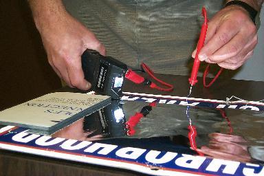
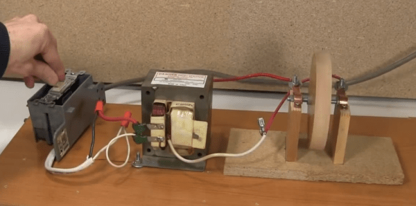
Commercial versions of the tool cost upwards of $600-$800 + lift film. The first hack they realized is that instead of using proprietary lift film, it is just as effective to use car window tint instead! The second hack is even more clever — using a 80,000V tazor, some electrical leads, and some tinfoil you can create your own version of the tool. The aluminum foil acts as a ground, and the object you are inspecting is sandwiched between it and the lifting film. Holding the tazor with one electrode to the foil, you can trace the film using the other electrode at a distance, which induces an electrostatic charge in the film, attracting and capturing the dusty fingerprints. Allow the static to discharge, and store the film in a safe place to be digitized later!

Now obviously this is only really effective for flat objects, but it’s still a brilliant hack — especially to save your budget!

[Thanks John!]

Automatically Sorting Beads By Color

beadsorter

[Tomas] wanted to try building something mechanical with electronic control, and ended up with this sorter that organizes beads into one of two containers based on color. He built most of the structure from popular interlocking plastic bricks, then added a stepper motor salvaged from an old scanner and two plastic discs.

The two discs sit on top of each other. The bottom one is stationary and has two holes drilled in it, with a container sitting below each hole. The top disc has a smaller, bead-sized hole and rotates from its starting position—where it collects one bead—to a camera for analysis. After the camera determines the color of the bead, the disc rotates again to position itself over one of the two sorting holes in the disc below, and the bead falls into the awaiting container. The device is controlled by the MSP430 microcontroller on a FITKit (translated), which is the development platform of choice for [Tomas’s] school.

[Tomas] originally attempted to determine the color of beads by using 3 different color LEDs and a light-dependent resistor, but switched to using a webcam and a Java program to capture images and calculating average hues. You can find more details and the source code on his site, but first see the short video below.

Continue reading “Automatically Sorting Beads By Color”

Designing Flip-Flops With Python and Migen

migen

Flip-flops are extremely simple electronic circuits, forming the basis of clock circuits, memory circuits, buffers, and shift registers. Through his dilly-dallying with digital logic, [Jeffrey] decided he would build his own. Not with Verilog or VHDL, though, but Migen: the Python-based way to build digital circuits with software.

Migen is an interesting tool that makes traditional FPGA programming a lot easier; instead of Verilog or VHDL, Migen allows an FPGA to be programmed in Python. Yes, it’s the tool you’ve been waiting for, and the tutorials make it look pretty easy. After installing Migen, [Jeff] wrote a class for a D flip-flop in only three lines of code. That’s three readable lines of code, and he was able to simulate the flip-flop with gtkwave in another two lines. Compared to learning the complexities of VHDL or Verilog, Migen makes digital logic and FPGA programming a breeze.

[Jeff] has a great tutorial for building a D flip-flop with Migen, but we’d love to see some more complex examples of what can be done with this very cool tool. If you’re building (or have built) something with Migen, be sure to send it in and relate your experiences.

Ask Hackaday: What’s Up With This Carbon Fiber Printer?

The Hackaday Tip Line has been ringing with submissions about the Mark Forg3D printer, purportedly the, “world’s first 3D printer that can print carbon fiber.”

Right off the bat, we’re going to call that claim a baldfaced lie. Here’s a Kickstarter from a few months ago that put carbon fiber in PLA filament, making every desktop 3D printer one that can print in carbon fiber.

But perhaps there’s something more here. The Mark Forged site gives little in the way of technical details, but from what we can gather from their promo video, here’s what we have: it’s a very impressive-looking aluminum chassis with a build area of 12″x6.25″x6.25″. There are dual extruders, with (I think) one dedicated to PLA and Nylon, and another to the carbon and fiberglass filaments. Layer height is 0.1mm for the PLA and Nylon, 0.2mm for the composites. Connectivity is through Wifi, USB, or an SD card, with a “cloud based” control interface. Here are the full specs, but you’re not going to get much more than the previous few sentences.

Oh, wait, it’s going to be priced at around $5000, which is, “affordable enough for average consumers to afford.” Try to contain your laughter as you click the ‘read more’ link.

Continue reading “Ask Hackaday: What’s Up With This Carbon Fiber Printer?”

Ball Bearing Motor Rolls For Reasons Unknown

[RimstarOrg] has brought us an oldie but goodie this week. He’s built a ball bearing motor, a design which has been causing engineers and scientists to squabble for decades. [RimstarOrg] used a microwave oven transformer with a 70 turn primary coil and a single turn secondary coil to create a low voltage, high current AC power supply. Needless to say, there’s a real risk of fire or electrocution with a setup like this, so be careful if you try this one at home. [RimstarOrg] then built the motor itself. He de-greased two ball bearings then installed them on a metal shaft along with a wooden flywheel. The entire assembly was then mounted on a board so the wheel could spin freely. Two copper straps hold the bearings to the board. Finally, the transformer is wired into the copper straps. In this configuration, the current will flow through the outer race of one bearing, through the balls, and into the inner race. The current then passes down the axle and passes through the other bearing. There is very little resistance in this circuit, so it can only be powered on for a few seconds at a time before things start to melt down.

Continue reading “Ball Bearing Motor Rolls For Reasons Unknown”

Heatsink Tester Shows Thermal Resistance Isn’t Futile

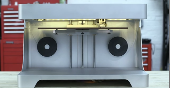
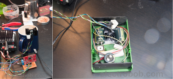
[Bogdan] knows that it’s hard to model the cooling needs of any given project. It’s important to know how much heat a system can dissipate given the housing material, airflow opportunity, and the proximity of neighboring components. Inspired by an aluminium-walled enclosure that allows for mounted transistors, he devised and built a heatsink tester.

He’s using an ATXMEGA32A4U, a temperature sensor, and a IRF540 MOSFET. A specific power is dissipated across the transistor, and the temperature sensor measures the heatsink as close as possible to the transistor. Through the serial connection, he gets back the supply voltage, current, calculated power, DAC set, temperature, and calculated thermal resistance in the terminal.

[Bogdan]’s tester assumes that it is reading the ambient temperature, so the circuit needs to warm up first. He found that an hour is generally long enough to reach this point. He also found that the system exhibits high thermal inertia, so it regulates the DAC output based on the dissipated power.

The Robot Operating System (ROS) 101

Ever heard about the Robot Operating System? It’s a BSD-licensed open-source system for controlling robots, from a variety of hardware. Over the years we’ve shared quite a few projects that run ROS, but nothing on how to actually use ROS. Lucky for us, a robotics company called Clearpath Robotics — who use ROS for everything — have decided to graciously share some tips and tricks on how to get started with ROS 101: An Introduction to the Robot Operating System.

The beauty of the ROS system is that it is made up of a series of independent nodes which communicate with each other using a publish/subscribe messaging model. This means the hardware doesn’t matter. You can use different computers, even different architectures. The example [Ilia Baranov] gives is using an Arduino to publish the messages, a laptop subscribed to them, and even an Android phone used to drive the motors — talk about flexibility!

It appears they will be doing a whole series of these 101 posts, so check it out — they’ve already released numéro 2, ROS 101: A Practical Example. It even includes a ready to go Ubuntu disc image with ROS pre-installed to mess around with on VMWare Player!

And to get you inspired for using ROS, check out this Android controlled robot using it! Or how about a ridiculous wheel-chair-turned-creepy-face-tracking-robot?