

I’ve been writing these tutorials on making an object in popular 3D modeling programs for a while now, and each week I’ve put out a call for what software I should do next. There is one constant in all those comment threads: FreeCAD. I don’t know if these suggestions reflect the popularity or difficulty of FreeCAD nevermind, it’s totally the difficulty.
FreeCAD is an amazing tool that, if used correctly, can be used to make just about any part, and do it in a manufacturing context. If you need a bauble that’s three times the size of the original, FreeCAD’s parametric modeling makes it easy to scale it up. If you’re designing a thumbscrew and want the head larger while keeping the threads the same, FreeCAD is for you. Basically, you can think of this as a graphical extension of the Thingiverse Customizer. Very powerful, very cool, and unlike a lot of CAD packages out there, free.
Our in-house, overpaid SEO expert (he’s really just a monkey someone trained to use a bullwhip) demands I link to the previous ‘Making a Thing’ tutorials:
The tutorial for FreeCAD continues below.
Our Thing
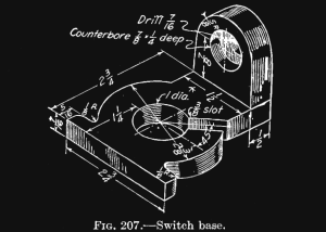 As with all tutorials, we’ll be copying this “thing”, taken from an 80-year-old textbook on drafting.
We won’t be copying this thing exactly – there’s a small taper on the tab with the counterbored hole – but we’ll get close enough so our finished model should be functionally equivalent.
Starting Up, And An Overview
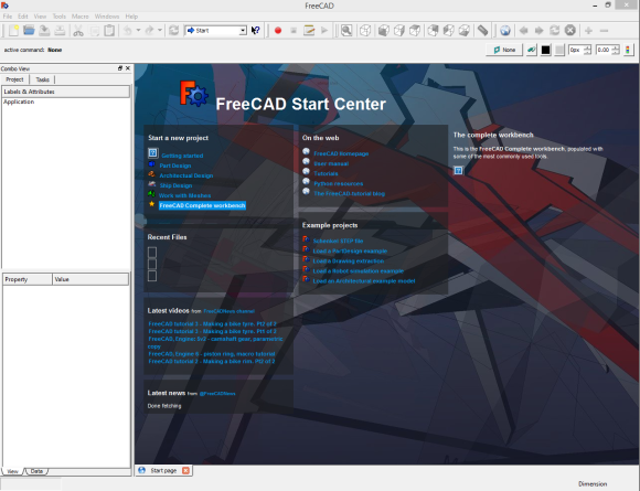
To use FreeCAD, you might want to download FreeCAD. It’s available for Windows, Linux, and OS X in 32 or 64-bit varieties. Pick your poison. After downloading and installing, you’ll end up with a “start center” that looks something like this:
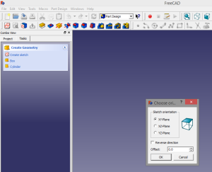 FreeCAD is unique among 3D design programs in that it has many different workbenches, or modes, to draw and model in. For most of our thing we’ll be using the Part Design workbench. Under the Start A New Project tab in the start page, click on the Part Design button. Hit Create Sketch, Choose the XY-Plane, and marvel at your drawing grid.
Before you begin, you might as well change the grid size to 1mm and turn on grid snap.
A word of note: While the grid size says millimeters, FreeCAD doesn’t really have units. Well, it has units, where one FreeCAD unit is equal to one FreeCAD unit. This is fine, because now we can design our part in eighths of an inch, where one eighth of an inch is one unit. It’s simpler, and to print out a correctly sized part we’ll need to multiply anyway…
If you read nothing else, read these two paragraphs
FreeCAD is a parametric modeler. This means all lines, figures, and subassemblies are defined by parameters and constraints. parameters are pieces of information that define a property of a part – a 10cm cube would have a parameter for the X, Y, and Z axes equal to 10cm. Constraints define the relationship between parts of an object. Two lines can be constrained to being parallel; move one vertex of a line, and a vertex of the constrained line will move as well.
Modeling an object parametrically is how companies can design many similar, but differently sized objects. A company that makes shoes may have only one model for every size of shoe. With parametric models, fabricating the parts for a run of size 6 and size 10 shoes may be as simple as changing a single number – the length from toe to heel.
Finally, Building
For most of our modeling, we’ll be working with two toolbars. They are the geometries and constraints toolbars:
![]()
The Geometries toolbar is what you would find in just about any CAD or drawing package. You have buttons for creating a point, an arc, a circle, lines and polylines, and even fillet and trim buttons.
![]()
The Constraints toolbar has buttons for locking an object (a line, circle, polyline, or what have you) onto the vertical axis and horizontal axis. In addition, lines can be made parallel, perpendicular, on a tangent to an arc, and the vertical, horizontal distances of a line, as well as the total length of a line or the radius of a circle may be constrained as well.
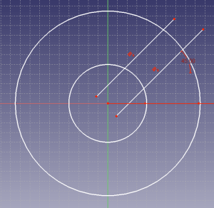
The first part of our ‘thing’ we’ll draw is the largest circle. Using the grid snap (or by pressing CTRL while moving the cursor around), draw a circle at 0,0 on the grid. This circle will have a radius of 9.5. We’re doing our units in eighths of an inch, and since the largest circle has a diameter of 2 3/8″, or 19/8″, the radius will be 9.5 units. Also add another circle with a radius of 4.
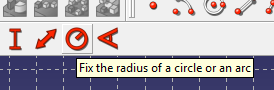 You can use the Geometries button to make these circles roughly to size, then use the radius constraint to make the circles the required sizes.
After you’ve drawn and constrained these circles, you should have something that looks like this:
Now for some detailing
 There’s still a lot to add to our ‘thing’. Let’s start with the 3/8″ wide slot. Start by drawing two lines roughly going from the center of the circles through the larger circle. Constrain them to be parallel, and the angle of one (the far right button on the Constrain toolbar) to be 45 degrees.
Using the Trim tool on the geometry toolbar, trim off all the excess – the ends of both lines, and the cutout on both of the circles. Now you should have something that looks like the letter C.
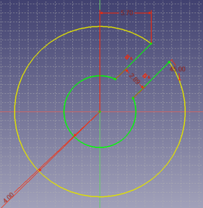
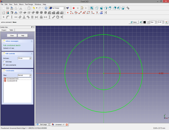
With the “Fix a length” constraint tool, make the distance between both of the 45 degree lines to be 3. Finally, lock the upper, outer vertex of the slot with the ‘Lock’ constraint. You should have something that looks like the pic to the right. You’ll also notice on the left-hand toolbar of FreeCAD the “Solver messages” says it’s a fully constrained sketch.
This means we’ve done this properly. Well, in this case that’s a bit of a lie (we haven’t guaranteed the slot is lined up with the center of the circles), but it’s close enough. In FreeCAD, the object is to have a fully constrained object. That’s what we’ve done here.
Since I like to keep these tutorials down to about 1000 words, I’m going to end this here. In the next installment of this tutorial, we’re going to add the flanges on this washer-type part, extrude it into the third dimension, and add the bit with the countersunk hole.
To be continued, and I’ll probably put a link to Part II right here.


Sweet, freeCAD is the one I wanted to see you working with in this series!
Ditto, thanks Brian, you’re a legend.
I noticed a discrepancy in the article. You mention setting the grid to mm, but then describe the geometry as if the units are 1/8″. Thought I’d point that out.
I’d also like to point out that in fact, FreeCAD does work with real units. Whatever you set your model units to, you can always add features that have a different unit — for example, if you want to add a hole for a 1/4″ camera tripod screw on a model that’s otherwise done in millimeters, when you go to dimension the hole for that screw, just type in ‘.25 in’ or ‘1/4 ” ‘ (mind the space between 1/4 and “) and FreeCAD will make it the appropriate size. Currently, it works by converting it to the part’s unit system, so a 1/4” feature in a part measured in mm will appear as 6.35, but if I’m not mistaken, the goal is to eventually leave the numbers alone and just append the correct unit.
Lastly, I want to note that if you want to do serious CAD work, eyeballing anything is unacceptable, unless you’re working on aesthetic features.
To make sure the slot is lined up with the center, just draw a construction line from the center of the circle, constrain one endpoint to be dead in the center of the circle, add your angle dimension, and constrain the lines for the slot against the line. It’s okay to just leave the construction line alone, as it won’t affect any 3D geometry.
Making good use of construction lines is an essential skill for any parametric modeler. In FreeCAD in particular, you can find the toggle in the Sketcher Geometries toolbar. The icon looks like this: http://www.freecadweb.org/wiki/images/2/2a/Sketcher_AlterConstruction.png
Anyway, that’s probably all I’ll ever write again, at least until Section 3 of the ToS is changed. Just wanted to bring up a few things because I happen to really like FreeCAD.
> Lastly, I want to note that if you want to do serious CAD work, eyeballing anything is unacceptable, unless you’re working on aesthetic features.
You’re right, but ‘eyeballing’ it is… two steps. Doing it properly is six, and I hate doing animated .gifs for these things. It’ll be correct in the next post.
> Anyway, that’s probably all I’ll ever write again, at least until Section 3 of the ToS is changed
Working on that.
I’m glad to see a FreeCAD tutorial, but I have to agree with Luke on both points. Copying and pasting his 1-sentence discription into the article would be allowable as fair use; just attribute the quote to the source. :)
By the way, I hereby reject your Terms Of Service and release all my past, present, and future posts under the Creative Commons “Attribution 4.0 International” liscense:
http://creativecommons.org/licenses/by/4.0/deed.en_US
Pft that stupid construction line! I used to work on Solidworks back in varsity, but now I love FreeCAD, all that I need that is missing is Assemblies and Construction lines. I knew I saw it somewhere though, now you helped me. Now to just get the assembly branch to compile….
Modeling environment looks a lot like CATIA…
There is a connection to CATIA:
(from http://en.wikipedia.org/wiki/Open_Cascade_Technology)
CAS.CADE (abbreviated from Computer Aided Software for Computer Aided Design and Engineering) was originally developed in the early 90s by Matra Datavision, editor of Euclid CAD software as the underlying infrastructure for its future version Euclid Quantum. In 1998 the company abandoned software development to concentrate on services, and most of the software development facilities were sold to Dassault Systemes, editor of competing CATIA. In 1999 Matra Datavision decided to publish its CAS.CADE infrastructure under an open source model and renamed it Open Cascade.
Other CAD software that uses Open CASCADE’s engine:
http://qtocc.sourceforge.net/links-related.html
You can keep the SEO experts away by repeating the magic words: “empirical evidence” when they come within earshot.
HeeksCAD is also free, and it would be awsome if I could get it to stop crashing in gnome….
Next give Creo Elements Modeling Express a go.
Its free, too.
Solvespace is another great free tool that’s parametric.
http://solvespace.com/
+1 for Solvespace.
I love how simple it is. I have used it a fair bit now but the one thing I have trouble with is the “trim” tool. It always seems to trim, but add more lines/points beneath my existing features.
It also is not quite as nice as other programs when it comes to assemblies.
1000 words ? You should at least make an extrusion example with your drawing… This tutorial ends on nothing.
But i’m glad to see something about Freecad ! I used it but I’ve found it can’t do assemblies (actually, it can but it’s not the best feature from Freecad) so I switched to a proprietary one. Would love to come back to Freecad with assemblies features (and better memory management with big drawings) !
FreeCAD is worthless because it only supports metric.
I thought metric was the preferred system on Industry
That really depends on the industry. And really, it depends on the company, contract, and personnel in question.
Bullshit. You can set units like any CAD program.
(Last post for reals this time.)
25.4
Multiple unit systems is only starting to be implemented in the development branch. It is not available in the current stable release. On the other hand, the whole damn world except for the USA works with the metric system. Obviously pcf11 is not aware of that fact or chooses to ignore it.
HeeksCAD was nice, but its development has stopped.
Any chance for http://brlcad.org/ at some point?
Hello, I’m interested in the name of the old textbook from which you found the example.
Engineering Drawing. French, 1929. 4Th edition. You might be able to find it in the newer French & Viereck editions.
I’m inexperienced in both FreeCAD and 3D modeling for 3D Printing and the combination of FreeCAD and this tutorial had me wanting to punch something. I’m probably doing it all wrong, but I ended up ending the task in Windows to make the program closed because it was in edit mode and couldn’t be exited out of. Aside from that, a lot of what you said to do was pretty inexplicable and I had to hunt for quite a long time to find out things like how to create a sketch and how to use the trim button. I messed up the trim button and never did figure out how to fix that. I also could not figure out how to make the parallel lines be a specific distance apart. Because I messed up the trim, my object remained unresolved.
Sorry if I seem like I am ranting, I just wanted to say that while I like the tutorials – a little more in-depth explanation might be wonderful as well as maybe something like putting bright squares around relevant buttons or things you have to click.
You were quite right about FreeCAD being difficult, but it also seems like it would be powerful enough to make quite complex things… if you can overcome the learning curve.
Thank you!
(TL;DR: I had issues.)
Sara, there are many video tutorials for FreeCAD on YouTube. Look them up.
That being said, granted it’s not as easy as Sketchup or Tinkercad. Constraint-based sketching requires getting used to. But FreeCAD’s focus is not on ease-of-use, but on being a powerful CAD platform.
On the other hand, you have a second method of creating 2D geometry, with the Draft workbench. It’s more along the lines of AutoCAD or LibreCAD.
OK, good to note! Not a beginners tutorial. I will look those up, thank you!
Since Brian posted this I’ve been meaning to create a videotutorial to show how this part can be modeled in FreeCAD and post it on YouTube. For now I just have quick tips over there, but others have more detailed tutorials, look for bejant0001 or Bram de Vries’ videos among others. I hope to record mine next weekend but I have a shitty mic input.
Also, the best place to get help on FreeCAD is the FreeCAD forum, we have a small but active community.
That would be welcome. I also tried to follow along with the tutorial, but ran into problems frequently. I got to the end and now when I try to put in the final constraint it complains that the constraint is redundant. If I remove the redundant constraints (one in the X direction, the other in the Y), it says the sketch is under constrained with 2 degrees of freedom. D’oh!
Seems buggy and difficult to use. The above guide was only a little helpful and I had to figure out a lot of stuff on my own.
I just wanted to say, this post has altered the course of my life.
I’ve been designing all kinds of models now and it all began with this post.
I really appreciate this style of learning, tutorial learning is far more useful than reading manuals to people like me.
Thank you for enabling me.
Starting to think that throwing money at 3d design to Autocad might be worth it….
Been rooting for about a week now that I have finally decided on a 3d printer and what a morass!!!
Starting from scratch (ancient draftsperson, some Autocad, fair at qcad (forget new name)) is frustrating, tutorials all assume far more knowledge than a newbie is likely to have.
My favorite so far: “…select inset faces with the tool tip pop up thingy”. Looked for that for a day and a half, old version? Blender docs and google we no help either.
Taking a break and working out frustration with another yummie pack of nails to chew on :-).
I shall preservere!!!!!!! :-).
So far I too have found the tutorials all seem to assume prior knowledge. I have no 3D drawing experience at all. It sounds like a new language to me. this tute is of no use to a newbie like me as I could not figure it out either. At least a picture of what icons to select for each function would help. One set of a 25 episode YouTube videos I started watching has a lot of “political” ranting in it so I quit that one. Am still looking. There are a lot of links to tutorials but how to select one that works is very hard. Can anyone recommend a good book?
Wonder if Autodesk is starting to get worried about this open source competitor to their professional Inventor software, getting closer to being a free piece of commercially viable software with every release?
Maybe someone should troll Autodesk by putting a FreeCAD tutorial on their Instructables site?
Thank you for this series — it’s a really great job comparing the tools.