
It’s time once again for another installment of a Making A Thing tutorial, where I design the same part, over and over again, in multiple 3D design software packages.
Last week we took a look at FreeCAD, a free, open source parametric modeller. It’s an amazingly powerful tool, and not it’s finally time to complete our model of a strange object ripped from the pages of an 80-year-old drafting textbook.
Here’s some links to previous Making A Thing tutorials, doe:
- OpenSCAD
- AutoCAD Part I
- AutoCAD Part II
- Blender Part I
- Blender Part II
- SketchUp
- Autodesk 123D
- FreeCAD Part I
Read on for the second part of our FreeCAD tutorial
Our Thing, And Where We Left Off Last Time
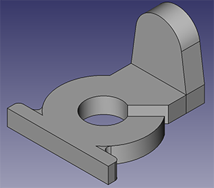
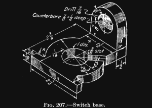 To the right is the thing we’re making. It’s from an 80-year-old book on drafting.
A few people have asked me for a .PDF of this book. My copy is in dead tree format, and I haven’t yet built a book scanner. If anyone out there has the 1st or 2nd edition of Engineering Drawing (French, 1911 or 1918), please scan it (its public domain) and post a link. Here’s the Google Scanned copy of the 2nd edition.
In the last installment of this tutorial, we went over installing FreeCAD, the basics of parametric modelling, and drawing a few circles and lines. Finishing off our ‘thing’ is just a process of drawing lines, arcs, and fillets, constraining them, and tearing your hair out at the inability of FreeCAD to show you the one unconstrained element in your sketch oh my god. After a little trial and error, we end up with something like the pic below, a fully constrained sketch of most of our switch base:
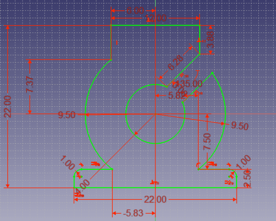
Yes, it’s ugly, but it’s accurate. Now it’s time to move on to the third dimension, extruding our thing up 7/16th of an inch. Note that I really don’t care about the absolute dimensions of what I’m designing. FreeCAD is metric only, so I’m designing everything around eigths of an inch. Slicers allow you to scale a print anyway…
Extrusion
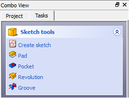
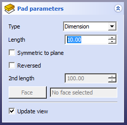
Once we have our part drawn and constrained, the Solver on the left hand toolbar will tell us we have a fully constrained sketch. Now it’s time to extrude our object. Click Close on the Tasks bar, and you’ll end up with a few options: Create Sketch, Pad, Pocket, Revolution, and Groove. The tool we use for extrusion is Pad, so click on that. Switch over to the isometric view, set the pad parameters for the correct depth of extrusion, and you’ll get an awesome filled solid. Awesome.

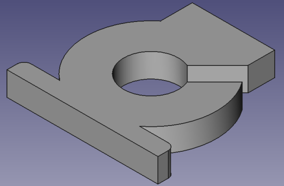
While we couldn’t do the ‘interior’ fillets on our part in the Part Design workbench – the fillet command only works between two lines, not a line and an arc. Now that we’ve extruded our thing into the Z axis, we can finally add those fillets. In the 3D view, click the edge separating the big ‘washer’ of our part and the long flange.

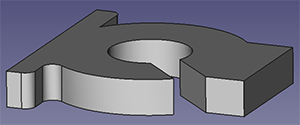
After that, we get a fairly good-looking part. We’re not done, though. We still need to make the other part of our thing, the ‘countersunk flange’, as I like to call it.
Adding Another Part
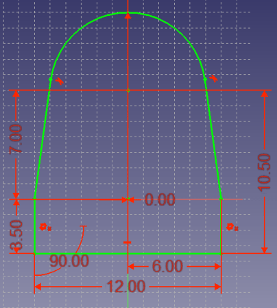
Right now we have the ‘bottom’ of our thing designed, but we’re still missing the flange with the countersunk hole. To add this, we’ll need to create the outline of the ‘countersunk flange’ part of our thing. Do that by going int the Part Design workbench, drawing a fully constrained part, and extruding it just like we did with the first part. When we’re done, we’ll have something that looks like this:
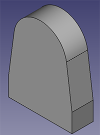
 With that done, it’s time to assemble these two parts. When we go back to the Part workbench, we’ll see something like the pic to the right. Our parts are there, but we’ll need to arrange them correctly and join them somehow. After that, we’ll need to put the holes in our flange. Easy enough.
Arranging The Parts
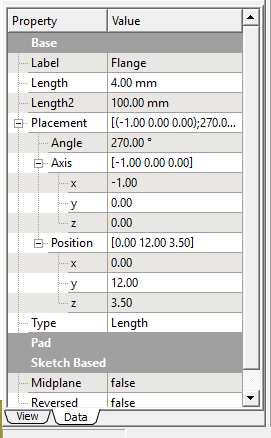
In the Part workbench, select the flange you just made in the part tree for our thing. There’s a tab at the bottom labeled ‘Data’, and this is where we’ll place our flange at the end of the ‘washer’ part of our thing. Play around with the position until everything’s correct, and we have 90% of our thing done.
Adding The Holes
Select the face on the flange we want to drill our holes into. We’ll need to create two sketches for this; one for the through hole, and a second for the counterbored hole. Sketch the smaller hole, then remove it with the Pocket tool. This tool is pretty much the opposite of the Pad tool; it extrudes “down” instead of “up”.
In another sketch in the face of the flange, draw the larger hole, and Pocket it down to the proper depth.

And there’s a completed part. Export, do some Booleans if you need to, and we’re done.
Wrapping Up FreeCAD
FreeCAD is an amazingly powerful tool, but in making this tutorial I did notice a little bit of wonkiness in the FreeCAD interface; using the middle mouse button to pan the sketch through the current view didn’t always work, adding a line sometimes (though rarely) results in freezes, and there were a few instances where the UX is just… crummy.
Seeing as how FreeCAD is currently in version 0.13, and possibly the fact that I’m using the Windows version, this sort of thing is to be expected. It’s still being improved, and although I believe FreeCAD will eventually become one of the best open source design and modeling softwares out there, it still needs a bit of work.
If you know Python and C++, and you’re looking for an open source project to contribute to, I’d highly suggest helping out the FreeCAD devs. There’s no doubt in my mind FreeCAD will eventually be as popular for mechanical and 3D design as KiCAD is for electronic design in a few years. FreeCAD is still a great package now, but it needs a little bit of work before going mainstream.
That’s it for this Making A Thing tutorial. Next week Hackaday contributor [Rich] will putting up the first part of a tutorial on Solidworks. It’s awesome, and you’ll read it.
After the Soildworks tutorial, I have absolutely no idea where these Making A Thing tutorials are going to go. Between the half-dozen software packages this series has covered so far, We’ve covered just about every method of creating an object to be 3D printed – AutoCAD for traditional drafting, FreeCAD for parametric modeling, and OpenSCAD for scripting 3D modeling.
Writing more tutorials for other software packages would only duplicate what this series already has done with less popular softwares. This means I’m sort of in a bind as to what to write next for these Making A Thing tutorials.
If you have an idea of what this series of tutorial should do next, drop a note in the comments. I’ve also considered getting a Printrbot Simple and showing all the ways a print can fail – and the ways to fix it. If you have a better idea, you’re always able to suggest something in the comments.


Wonkiness. I will try. Looking forward to the Solid works. Thanks for all of these tutorials.
Agreed, thanks for doing these. Seeing how all the different CAD packages approach the same part is very interesting.
Please do Designspark Mechanical
I just got done learning Designspark PCB, coming from Protel 99se. For free software, it seems to work quite well to me, and more intuitive than Eagle. The autorouting could be improved upon a bit, but since I almost always route by hand, that is not an issue for me.
A series on Designspark Mechanical would be awesome….
I’ve been learning DesignSpark Mechanical. Once you learn the ropes, it is fantastic for direct modeling. Kind of like SketchUp, but you end up with a manifold object ready to print, rather than a hole filled monster mesh…
Engineering Drawing. You can download a PDF.
http://books.google.com/books?id=6R5DAAAAIAAJ&pg=PA78#v=onepage&q&f=false
Covers some programs that can do mechanical simulation as well to test out a design before committing it to print.
It would be extremely useful to take a quick tour around software that can do stress simulation so you can identify what the weak points of the design are.
Yes, and while it is doing that stress testing for you, it should make you coffee and wash up the dishes too.
After that it can redesign your part for you so you do not need to do the actual work anymore, so you have time to take up another job to pay your yearly SW subscription.
I have had a play with FEM programs before and they can be a bit tricky to get the hang of, so I definately with Dax. Although the 3D printing process will cause weaknesses in the material that will not be accounted for in the FEM software, it would certainly be a good indicator of where the design needs work.
Just for being rude, you can make our coffe and wash the dishes. We’ll also let you know any changes we’ll need you to implement when we see the results.
Will there be an article on solidworks? I am currently learning it in Engineering school right now with next to no instructions other than the professor telling us to “just watch cadjunkie on YouTube” … Feels great to pay tuition to watch YouTube videos!
Yep. Solidworks next Tuesday or Wednesday.
At least this way you’re paying tuition to read Hackaday.
Haven’t used Solidworks for two years, but back when I learnt it I had a proper tutor that I surpassed in two or three weeks just by going through the tutorials. Unless they’ve changed it recently, Solidworks tutorials are better than any teacher, at least for the basic stuff.
“I’ve also considered getting a Printrbot Simple and showing all the ways a print can fail – and the ways to fix it”
_”all”?_ My dear boy, from what I’ve seen, that would be a life’s work. Though perhaps “101 ways to get your print to stick” would be a good start, and probably cover the main cause of print failure (this is from an ABS user, mind you).
I’d like to see the free version of Creo (Pro/Engineer), though that’s mainly just because I use a spin-off version of it from about ten years ago.
You can download as DJVU:
https://ia700504.us.archive.org/13/items/amanualengineer01frengoog/amanualengineer01frengoog.djvu
Your “Countersunk Flange” Could have been made as a sketch on the face of the part you were strategically placing it next to.
Nice guide, and just what I need!
But how would I now go about transforming this part into a CAD mould for casting?
Is it possible to make a sort of “negative” of a 3d-shape?
Yeah, just put a giant box in there and subtract the actual part from the box. You’ll need to add some sprues and gates, and probably a parting line, though…
I just dunno why wasn’t flange made with another sketch – instead with playing with moving it. (Or either weren’t made in two parts and assembled – even though it’s still pain in FreeCAD)
Brian the guide was not entirely clear. The flange should have been sketched in the XZ plane. This way, you are already 90 percent aligned (assuming you build off 0,0 centered and moving upwards). You then need only push the part back in the Y. Also, the center hole can be ‘pre bored’ in the sketch, leaving only the shoulder to be cut out with primitives.
The sketch should have been made on the face it attaches to, not just on the xz plane. That would have solved the alignment issue
You know, I know, just why it’s not like that? Or assigned in assign module? This whole series is a bit messy for me :)
For the next part of the series, how about some articles on how to get from your CAD file to a physical object – different ways to get the files needed to print, and maybe a few pointers on what you would need to do to mill it.
To complete the series(in addition to the suggestions above), it would seem appropriate for a recap article that compares the previously reviewed packages, weighing the pros and cons of each.
I think that having the six most popular packages covered is a great start, but needs to go somewhere, so making something that’s actually useful. something that people can draw, and then press print on their 3d printer.
so my suggestion
Make a herringbone gear.
Start with package 1 again showing how to draw these components in each of the packages.
Then do the same thing with a different part.
Basically, the idea for what I’m saying comes from this simple statement.
it’s great to teach people how to use the software, but the tutorials so far have barely scratched the surface. and don’t really teach much past what the start-up tutorials likely included as animations with the packages would have taught anyway.
so step it up, get a more complex part and introduce more features.
Do some KiCAD after SolidWorks… You’ll need a new thing, but a series on PCB design would be cool, I could finally learn to stop using Fritzing.
Great series! If you’re still adding to it, it would be great to see the part created with Fusion 360, they have a free subscription level, especially useful comparison now that you’ve done Solidworks.
Thanks, Bruce! Hey, hackaday – I’m the community manager for Fusion 360. As Bruce said, Fusion 360 is free for enthusiasts (i.e. you’re not using Fusion for commercial purposes), and actually has a MakerWare plugin. Shout with any questions!
“…tearing your hair out at the inability of FreeCAD to show you the one unconstrained element in your sketch oh my god.”
Describes my situation exactly. I finished the first drawing in a few minutes. It was “fully constrained”. But as soon as I trim the first line out of it the whole thing goes to heck. I worked for hours to get a “fully constrained” drawing without internal lines. No luck. The closest I get could was two unconstrained elements. I give up! Seems like the developers need to work on the foundation before adding curtains.
Thanks for this, but… Dang! I was rather hoping that instead of saying “Play around with the position until everything’s correct”, you were going to show me how to constrain two objects to be adjacent to each other :(
If you feel you have covered making an object, how about some comments on slicers?
FreeCAD can use inches… set it in your preferences.
i could help you writing the tutorial of the same part in openscad, anyone interested?
wow this is hard work to get step one of this fully constrained now for the second bit!!
Finally got around to follow this Introduction. Well done!