Flickering candle LEDs are seemingly everywhere these days, and like all fads, someone has to take a very close look at the engineering behind them.
[cpldcpu] had earlier taken a look at the controller chip in these candle flicker LEDs by measuring the current used and developing a statistical model of how these LEDs flicker. That’s math, of course, and much more fun can be had by decapsulating one of these flicker LED controller chips. It’s not very advanced tech; the LED controller is using a 1 or 2um process and a pair of RC oscillators, but it appears there could be a hardware random number generator in the silicon of this chip.
Earlier, [Cpldcpu] had taken a look at the tiny controller in these flickering LEDs and determined they used a linear feedback shift register to generate pseudorandom LED intensities. The new teardown seems to confirm that a linear feedback shift register is being used to drive the flickering LED.
Custom chips are only one way to skin a cat, or flicker a LED, and PICatout used the the tiniest PIC microcontroller (French, translation) to create his own flickering LED. Seems like making a few custom flickering LED throwies shouldn’t be too hard.


To be honest. Not all candlelight leds are that complex. I’ve once seen a LED that’s flickered by substituting the speaker with a LED in one of those musical cards.
Indeed, some flickering leds use the music chips. see http://www.instructables.com/id/Listen-to-a-led-tea-light/
That is interesting. I think the LFSR approach is simpler. It is easily implemented in silicon, doesn’t require any storage, or any preprocessing to preload the music.
If you were talking DIY where you were building it all yourself, then sure, but if you are talking about a commercial self contained product, then the music chip is more complex and probably more costly. Remember the LEDs we are talking about have this chip built inside the LED.
Its not about complexity, its about being a self contained package. The space all the extra parts occupy is more expensive than an all in one solution.
I see LFSR used for this a lot, but I don’t understand how the output of that is then used to control the LED. Is it used to vary the duty cycle with PWM? Something else?
This one uses PWM:
http://cpldcpu.wordpress.com/2013/12/08/hacking-a-candleflicker-led/
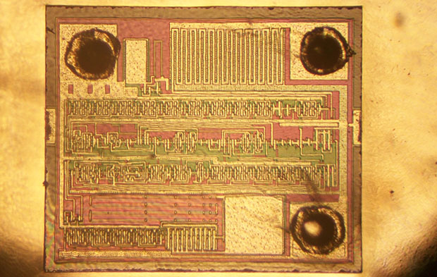
The only two samples that I had of the die pictured above were destroyed in the process of removing the metal layer, but they did yield a lot of information. In tracing out more of the circuit here’s my best take:
The main clock oscillator is divided down through a series of stages. Later, one of these lower frequency clocks is used to drive the LFSR (which is a series of shift-registers with a few exclusive-or gates strategically thrown in). A few (three, I think) bits from the LFSR are used to select different taps from the divider chain. This gives a series of PWM pulses which (thru the large buffer transistor) ultimately drive the LED die. This is rapid enough that the human eye will perceive the different PWM duty cycles as simply different LED intensities. The pseudo-random nature of the LFSR switches between the various PWM selections a few times each second. This emulates the random perturbations of a candle flame flickering as it struggles to survive on a windy night.
The second point that I’ll make is that these two chips have a lot in common than might initially appear. While the process is clean, it’s pretty crude by modern standards. It appear to be about 2um, and from what I can tell, it’s a metal-gate CMOS process.
My photograph (shown at the top of this post) is blurry, but one can easily see that the same basic cell that is used thru-out this design, is nearly identical to the cell shown on Andrew Zonenberg’s micro-photo.
http://siliconpr0n.org/archive/doku.php?id=azonenberg:unknown:candleflicker_led
On Andrew’s photo, the very top row of the chip has the cell repeated 5-times (2-cells, then a space, then 3-cells). Roughly that cell is repeated 30 times throughout his chip. On the one I dissected, that same cell is repeated a similar number of times. So on that point I disagree with Mr. CpldCpu’s assessment that Andrew’s chip does NOT use LFSR, based in part because he does not see more than 5 of these cells. I see approximately 30, which is more than enough to implement a similar LFSR & Divider design that I described earlier.
The cell in question consists of a master-slave section that can be wired in different ways. In one instance if forms a D-Flip-Flop and is used in series to form a divider chain to divide down the clock frequency (to generate the PWM clocks). In a different configuration the master-slave sections are wired to form a shift-register to implement the stages of the LFSR (Linear Feedback Shift Register).
It’s unfortunate that neither chip have either manufacturer’s logos or part numbers, but given the fact that the same cell layout is used, I wouldn’t be surprised if they share a common heritage; perhaps even the same designer or manufacturer..
Awesome! Nerd fight! :)
>The second point that I’ll make is that these two chips have a lot in common than might >initially appear. While the process is clean, it’s pretty crude by modern standards. It >appear to be about 2um, and from what I can tell, it’s a metal-gate CMOS process.
Indeed, there are some indications for this:
– source/drain and gate area look identical after M1 etch
– Gate area is covered with M1 without clearly visible poly contacts. This is actually quite strange.
But then:
– Metal gate CMOS requires relatively high supply voltages due to high Vt. These chips work down to 3V and less.
– You can see that there is a third layer apart from M1 and junctions in the delayered images. For example right above the “A”.
– Why would anybody do a metal gate CMOS process in 2014? I understand that poly adhesion was a problem back in the 1960ies, but that was pretty much solved about 40 years ago.
>On Andrew’s photo, the very top row of the chip has the cell repeated 5-times (2-cells, >then a space, then 3-cells). Roughly that cell is repeated 30 times throughout his chip. >On the one I dissected, that same cell is repeated a similar number of times. So on that >point I disagree with Mr. CpldCpu’s assessment that Andrew’s chip does NOT use >LFSR, based in part because he does not see more than 5 of these cells. I see >approximately 30, which is more than enough to implement a similar LFSR & Divider >design that I described earlier.
Well, there are plenty of flip flops on both chips. But taking a closer look, they are arranged in a number of different configurations – ripple counters, shift registers and parallel registers. Merely looking at the number of flip flops does not answer any questions, it would be interesting to understand what each output does. Even with a hardware RNG a large number of flipflops is required, so the mere presence of them does not indicate anything. It still begs the question what the second RC oscillator is for.
>It’s unfortunate that neither chip have either manufacturer’s logos or part numbers, but >given the fact that the same cell layout is used, I wouldn’t be surprised if they share a >common heritage; perhaps even the same designer or manufacturer..
I wonder why there are different version. Did you try to record the pattern of your LED? There must be a reason to switch to the more complicated variant.
>CpldCpu’s assessment that Andrew’s chip does NOT use LFSR, based in part because he does not see more than 5 of these cells.
I should clarify this – there isn’t a group of more than 5 identical cells in a row. If you take a closer look, there are several rows with 4 to 5 cells, but all them them are connected in slightly different configurations.
The design, as reverse engineered from the statistical analysis, requires at least a 5 bit counter (frame counter), a 4 bit counter (PWM) and a 4 or 5 bit register (current brightness value). That would already account for 13 to 14 flip flops even without a RNG.
Google translate is really bad!
It got me thinking, could I convert the very similar flashing SMD 0805 LEDs (also with a pad spare but a different pad) into a flickering LED using a laser to fuse the adjacent pad?
Come to think of it, “editing” the circuitry with a laser would be fairly amusing.
Also on the projects list: I determined that feeding one with random data makes it behave strangely.
It shouldn’t be hard to use it as part of a random astable with LED connected between the capacitors and then make a R/O/Y random flicker circuit.
Wouldn’t be as good but makes up for it with tiny size.