Bringing The Quake Flicker To Life With A Hacked Light

If you ever feel a pang of shame because you’ve been reusing the same snippets of code in your projects for years, don’t. Even the big names do it, as evidenced by the fact that code written to govern flickering lights back in 1996 for Quake is still being used in AAA titles like 2020’s Half-Life: Alyx. In honor of this iconic example of digital buck-passing, [Rodrigo Feliciano] thought he’d port the code in question over to the Arduino and recreate the effect in real-life.

Since the Quake engine has been released under the GPLv2, it’s easy to pull up the relevant section of the code to see how the lighting was configured. Interestingly, lighting patterns were implemented as strings, where the letters from a to z referenced how bright the light should appear. So for example, a strobe light that goes between minimum and maximum brightness would be written as “aaaaaaaazzzzzzzz”, while a flickering light could be represented with the string nmonqnmomnmomomno“.

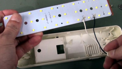
An emergency light provided the LEDs and enclosure.

This ended up being very easy to implement on the Arduino in just a few lines, as [Rodrigo] simply had to assign each letter in the string a numerical value between 0 and 255 using map, and then use the resulting number to set the LED brightness with analogWrite.

With the code written, [Rodrigo] then had to put the hardware together. He stripped down a basic emergency light to get an array of white LEDs and a handy enclosure. He also wired up a simple transistor circuit on a scrap of perfboard so the Arduino Pro Mini could control all the LEDs from a single GPIO pin. Combined with a long USB cable to power it, and he’s got a perfect desk accessory for late-night gaming sessions.

In the video below you can see the final result, which [Rodrigo] has even synced up to footage from the classic 1996 shooter. The light makes for an interesting conversation piece, but we think the logical next step is to work this technique into an ambilight-like system to really make it feel like you’re wandering down those dimly lit corridors.

Continue reading “Bringing The Quake Flicker To Life With A Hacked Light”

Small sensor built into audio jack, held in tweezers

Measuring LED Flicker, With Phototransistor And Audio App

No one likes a flickering light source, but lighting is often dependent on the quality of a building’s main AC power. Light intensity has a close relation to the supply voltage, but bulb type plays a role as well. Incandescent and fluorescent bulbs do not instantly cease emitting the instant power is removed, allowing their output to “coast” somewhat to mask power supply inconsistencies, but LED bulbs can be a different story. LED light output has very little inertia to it, and the quality of both the main AC supply and the bulb’s AC rectifier and filtering will play a big role in the stability of an LED bulb’s output.

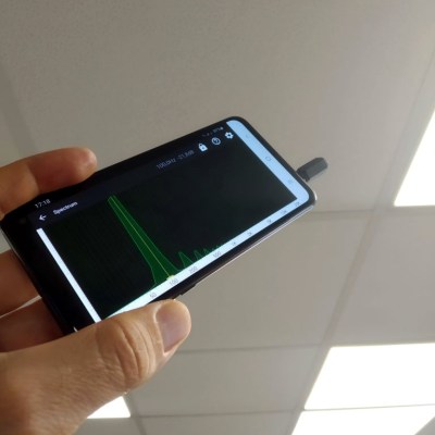
Mobile phone spectrum analyzer pointed at light source
The DIY photosensor takes the place of the microphone input.

[Tweepy] wanted to measure and quantify this effect, and found a way to do so with an NPN phototransistor, a resistor, and a 3.5 mm audio plug. The phototransistor and resistor take the place of a microphone plugged into the audio jack of an Android mobile phone, which is running an audio oscilloscope and spectrum analyzer app. The app is meant to work with an audio signal, but it works just as well with [Tweepy]’s DIY photosensor.

Results are simple to interpret; the smoother and fewer the peaks, the better. [Tweepy] did some testing with different lighting solutions and found that the best performer was, perhaps unsurprisingly, a lighting panel intended for photography. The worst performer was an ultra-cheap LED bulb. Not bad for a simple DIY sensor and an existing mobile phone app intended for audio.

Want a closer look at what goes into different LED bulbs and how they tick? We have you covered. Not all LED bulbs are the same, either. Some are stripped to the bone and others are stuffed with unexpected goodness.

How Constant Is Your Choice Of Lights?

The move from incandescent filament lamps to fluorescent, and then LED lighting over the last couple of decades has delivered immense benefits in terms of energy saving, but had brought with it problems for people sensitive to flicker or to too much of a particular set of wavelengths. It’s not always easy to quantify the propensity of a particular light for flickering. So [kk99] has produced an instrument returning a visual indication of its quality.

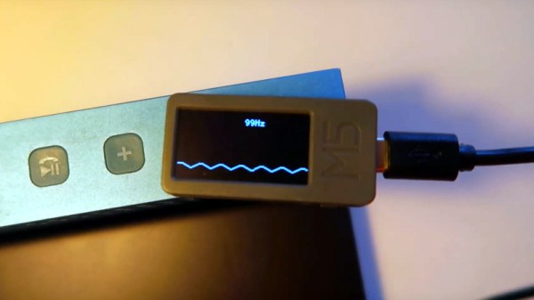
At its heart is an M5Stick ESP32 development platform, and a TSL250R light sensor hooked up to one of the ESP’s internal ADCs. The flicker waveform is displayed on the screen as a simple oscillograph, and a Fourier transform is performed to extract its frequency. The result is an extremely accessible and compact instrument, showing the suitability of the M5Stick form factor for such designs. So far we’ve only brought you an M5Stick in a password keeper, but we look forward to seeing more projects featuring it.

You can see the light flicker meter in action in the video below the break.

Continue reading “How Constant Is Your Choice Of Lights?”

Unphotogenic Lighting As A Feature

Have you ever taken a picture indoors and had unsightly black bars interrupt your otherwise gorgeous photo? They are caused by lighting which flickers in and out in its normal operation. Some people can sense it easier than others without a camera. The inconsistent light goes out so briefly that we usually cannot perceive it but run-of-the-mill camera phones scan rows of pixels in sequence, and if there are no photons to detect while some rows are scanned, those black bars are the result. Annoying, right?

What if someone dressed that bug of light up as a feature? Instead of ruining good photos, researchers at the University of California-San Diego and the University of Wisconsin-Madison have found out what different frequencies of flicker will do to a photograph. They have also experimented with cycling through red, green, and blue to give the effect of a poorly dubbed VHS.

There are ways an intelligent photographer could get around the photo-ruining effect with any smartphone. Meanwhile DSLR cameras are already immune and it won’t work in sunlight, so we are not talking about high security image protection. The neat thing is that this should be easy to replicate with some RGB strips and a controller. This exploits the row scanning of new cameras, so some older cameras are immune.

“Reverse engineering” a real candle

Reverse Engineering A Real Candle

[cpldcpu] just can’t leave the mysteries of candles alone. We’ve covered his explorations of candle flicker LEDs before, but this time he’s set his sensors on the real thing. [cpldcpu] hooked a photodiode to his oscilloscope, pointed it at a candle flame, and recorded the result.

The first interesting observation was the candle slowly changed brightness, whether it was interacted with or not. Next he measured the effect when the flame was disturbed by small gusts of air. This produced a bright flicker with an oscillation at 5Hz before returning to steady state, which as [stygiansonic] mentioned in a the Hacker News comment, is a known phenomenon used in flame detectors. Neat! There’s even an equation:

Under normal gravity conditions, the flames have a well defined oscillation frequency which is inversely proportional to the square root of the burner diameter, D, and to a good approximation can be written as f » 1.5/D½, with D given in meters.

[cpldcpu] then compiled his measurements into a series of graphs and ultimately an animated gif comparing the candle steady state, a real candle’s flicker, and the flicker he recorded from a candle flickr LED. It’s surprising how different the fake is from the real thing. You can look at his measurements and code at his github.

[via Hacker News]

Reverse Engineering Candle Flicker LEDs, Again

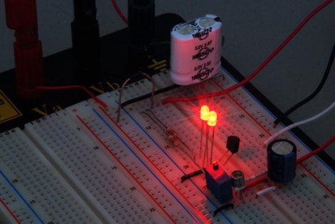
Flickering candle LEDs are seemingly everywhere these days, and like all fads, someone has to take a very close look at the engineering behind them.

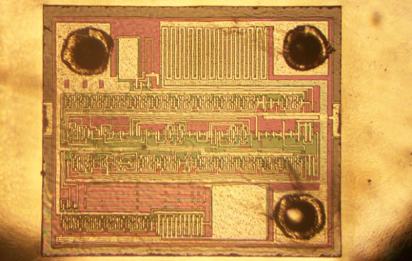
[cpldcpu] had earlier taken a look at the controller chip in these candle flicker LEDs by measuring the current used and developing a statistical model of how these LEDs flicker. That’s math, of course, and much more fun can be had by decapsulating one of these flicker LED controller chips. It’s not very advanced tech; the LED controller is using a 1 or 2um process and a pair of RC oscillators, but it appears there could be a hardware random number generator in the silicon of this chip.

Earlier, [Cpldcpu] had taken a look at the tiny controller in these flickering LEDs and determined they used a linear feedback shift register to generate pseudorandom LED intensities. The new teardown seems to confirm that a linear feedback shift register is being used to drive the flickering LED.

Custom chips are only one way to skin a cat, or flicker a LED, and PICatout used the the tiniest PIC microcontroller (French, translation) to create his own flickering LED. Seems like making a few custom flickering LED throwies shouldn’t be too hard.

Discussing Pulse-Width Modulation

[Michael Kleinigger] posted a lengthy discussion on Pulse-Width Modulation that goes beyond the traditional beginner tutorial. He starts a bit of background info on PWM and a tip about using a camera to judge frequency and duty cycle of LEDs. From there it’s down the rabbit hole with some testing of power-loss versus frequency.

When you change from frequencies of 50 Hz to 1 MHz how does the parasitic power loss from switching affect the overall efficiency of the circuit? It turns out there’s a rather large amount of loss at the highest level, around 1.5 mW. The greatest balance of low power loss and elimination of flicker seems to be right in the 300-500 Hz range.