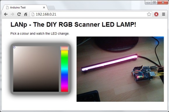
Being able to use one of your old projects to make a new one better can be quite satisfying. [Steve] from Hackshed did just this: he integrated an Arduino based webserver into a new network controllable RGB lamp.
What makes this lamp unique is that the RGB LED bar comes from an old Epson scanner. Recycling leftover parts from old projects or derelict electronics is truly the hacker way. After determining the pinout and correct voltage to run the LEDs at, the fun began. With the LED bar working correctly, the next step was to integrate an Arduino based webserver. Using an SD card to host the website and an Ethernet Arduino shield, the LEDs become network controllable. Without missing a beat, [Steve] integrated a Javascript based color picker that supports multiple web browsers. This allows the interface to look quite professional. Be sure to watch the lamp in action after the break!
The overall result is an amazing color changing lamp that works perfectly. All that is left to do is create a case for it, or integrate it into an existing lamp. This is a great way to use an LED strip that would have otherwise gone to waste. If you can’t find a scanner with a color wand like this one, you can always start with an RGB strip.


Actually, it was a Canon scanner not an Epson.
Anyway, is this a common thing?? That scanners have rgb-ledbars in them??
I have one of those multi printer/scanner/etc in my basement and I was about to throw it out. I might rip it apart and take out the motors. But if it has a ledbar like that one I know one more thing I’m gonna keep.
Most consumer grade multifunction printers will use this type of scanner. Older and more expensive multifunction printers will use CCDs and lamps but contact image sensors with RGB leds are most common now. The LED almost never fails (always the delicate bond wires to the sensor or the sensor itself) so faulty ones might be a good source.
all new ones do, older ones use ccfl bulbs which are good for a small high voltage transformer circuit anyways. I’ve used both, though more of the CCFLs as people give away newer scanners less, but they are fun to mess around with. I made a laptop powered light during a power outage with one, they work nicely on 5v.
There is a scanner type called “CIS” (Contact image sensor) that have a sensor array on the moving lamp tray, they are using RGB light because they accually scan one color at a time.
Google for CIS scanner and you’ll find pictures of the technology. The other type is called CCD scanner and uses a stationary CCD sensor with mirrors and stuff.
The Canon LiDE scanners are RGB, and have been around forever.
Mine is so old it’s uses USB v1 (but has Win7-32 (Ok XP) drivers). Still works, so eh.
This is really cool! I think i’d rather use those generic IR/RF RGB bulbs and somehow interface the arduino with it. But using what you have to hand is always good too!
An Arduino turning on and off a LED, how original. Why dont you guys throw it on top of the pile of 1000 other Ardunio+LED projects you’ve shown here.
inb4 b-b-but its network controllable. It doesnt matter, it is still nothing more than a excuse for someone to justify dumping $50 on a Ardunio.
Sorry the FREE content didn’t entertain you. I, for one, think this is pretty sweet.
Yea if u purchase genuine arduinos.. but who does that anymore?
It’s actually a good way of finding another use for the ardunio you already own. Don’t forget that the arduino is simply a development platform and once you’re happy with the design, you dump it onto a single Atmega chip to leave in the project. Yes, there are 37849374893 other arduino projects online but that’s only testament to the success of the arduino itself and the way the arduino team have opened up microcontrollers to the masses instead of men with beards and obvious geniuses like yourself Matt.
I am doing a project with an HP OfficeJet 5610 All-In-One. I’m trying to remove the scanning light bar and interface it with an Arduino or Raspberry Pi to recreate the scanning capabilities of the device on a non-HP controller. Do you guys have any tips on how to best determine the pinout and voltages of the scanning component? It is currently connected to the HP board via a 9 pin ribbon cable.
I know I am responding rather belatedly; but the simple way is to look at the ribbon connector on the mother board the ribbon cable connected to and trace out the power connection and the 3 wires that will be connected to a transistor based driver circuit with at least 3 decent wattage load resistors. Pro-tip : most of the bars I have taken from various led type scanners have the 3 color connections at the beginning of the connector. {most bars have the connector really close to the LED and 3 surface traces leading to the ribbon connector. typically there are 5 connections, think one is ground the other is vcc and the other 3 are for the led drive connections. You can pretty much get away with using the vcc and 3 LED color connections as is, there might be a kind of sense setup built into the LED module, but I have yet to get a source info on the thing to be sure. Cheers!
Do these lamp/bulb modules have built in current limiting resistors or do I need to add them?
Also, any tips on finding optimal voltage?