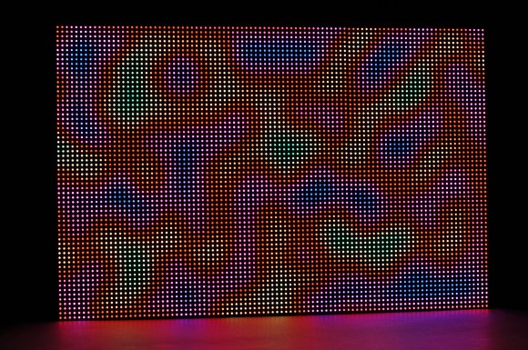
This is 6,144 RGB LEDs being controlled by a BeagleBone Black and a FPGA. This gives the display 12 bit color and a refresh rate of 200 Hz. [Glen]’s 6 panel LED wall uses the BeagleBone Black to generate the image, and the LogiBone FPGA board for high speed IO.
[Glen] started off with a single 32 x 32 RGB LED panel, and wrote a detailed tutorial on how that build works. The LED panels used for this project have built in drivers, but they cannot do PWM. To control color, the entire panel must be updated at high speed.
The BeagleBone’s IO isn’t fast enough for this, so a Xilinx Spartan 6 LX9 FPGA takes care of the high speed signaling. The image is loaded into the FPGA’s Block RAM by the BeagleBone, and the FPGA takes care of the rest. The LogiBone maps the FPGA’s address space into the CPU’s address space, which allows for high speed transfers.
If you want to drive this many LEDs, you’ll need to look beyond the Arduino. [Glen]’s work provides a great starting point, and all of the source is available on Github.
[Thanks to Jonathan for the tip]


Damn… that’s exactly what I wanted to do a couple of years ago! congratulations!
Idea for future improvement: add a dvi port to connect it to your computer
There’s already a full linux box there in the beaglebone black. Why would you want to connect it to another computer? Just wondering why you want that?
fair point…. would have been nice to use it as a bright external screen
If the wall were higher resolution, I’d definitely want to use a video card with some GPUs to drive the panels via HDMI or DVI but for this smallish ”wall,“ the BBB works great and lets me mount the panel anywhere without having to drag along a PC.
DVI ports are actually pretty easy, they need little more than a socket, 8 wires and some logic on the FPGA. You could drop the BeagleBone completely from the design.
I will have to give DVI a try! Thanks for the tip.
DVI uses the same signalling protocols as HDMI, and there is sample source for that over here http://www.fpga4fun.com/HDMI.html
Exactly what I wanted to do at the time :)
At 600x400mm, although it’s impressive, it’s not exactly a ‘wall’…
When I used to work as a stagehand I dealt with plenty of what I remember as 20×15 arrays of 8×8 LED blocks, roughly 2000x1500mm overall. Maybe 20 or more of these would be assembled together to create giant video backdrops for the performer. 6000 LEDs here is crazy, but 384000+ is insane. Some LED manufacturer must be making big money from the entertainment industry…
The most impressive video wall installation I’ve seen is the Comcast building lobby in Philadelphia. It’s the world’s largest 4mm pitch LED video wall w/ ~10 million RGB LEDs.
So… the FPGA does all of the hard work and the BBB (Dark Ritual) just generates the image and passes it off to the FPGA, which does all of the heavy lifting?
Exactly. For example, the software to display a static image pushes the image into the FPGA over the GPMC bus then quits. The FPGA drives the panels from there.
A perfect example of why you might want to marry an FPGA with an embedded Linux system. The BBB is just sitting there waiting to do all kinds of cool visualizations without having to bother with the particulars of driving the display.
Pretty much, yes. FPGAs are good at high speed IO with precise timing. Better yet they are inherently highly parallel, so rather than bumping up the clock further he could have set up a second data bus and run that in parallel with the first.
What they are less good at is complex control logic, which is why it is common to implement a soft CPU core in an FPGA design for that kind of work, or with the latest ZINQ/ Cyclone V designs include one or more hard ARM cores on the chip.
One common task for an internal CPU core is running a complete TCP/IP networking stack. This is often less expensive than adding an external CPU to the design to run the same networking stack.
Actually, it is not as impressive as it looks. FPGA can drive things way faster than this. I am myself waiting for such panels to test a 15 bit color output, and i had to use a very slow clock to drive them without much noise. When it arrives and after some tests I’ll publish some info.
Alvie
ZPUino project
http://www.alvie.com/zpuino
Wondering if the BBBs PRU was an option to replace the FPGA – http://www.element14.com/community/community/knode/single-board_computers/next-gen_beaglebone/blog/2013/05/22/bbb–working-with-the-pru-icssprussv2
Not sure if it was up to the job but this seems like the sort of thing it’s good at.
The PRU will do it but the refresh rate is quite a bit slower which can be a problem if you’re sensitive to flicker or are photographing or filming the results. See @qrs on twitter for details on using the PRU to drive these panels.
Not entirely true… here is PRU firmware to run LED panels at 100 fps (hardware limitation of the LEDS) https://github.com/mranostay/ws28xx-lighting-pru with a few blogs posts documenting it here -> http://ranostay.blogspot.de/
Not the same thing at all. That source is to drive WS28xx LEDs, which have their own onboard 8 bit per colour PWM. You feed them a serial data stream @800Kbit/sec and they do the rest themselves.
This, on the other-hand, has non-PWM LEDs that are effectively being PWM’d by a 25MHz parallel data stream from the FPGA, so about two orders of magnitude slower.
Ooo. Boxing in the leds with opaque boxes and frosted glass covers would make a wicked plasma effect.
Good idea! Might have to run to the local plastics dealer and get a sheet of frosted acrylic and give it a try.
Just been on NAB2014 where I did see a LED wall from http://www.silicon-core.com/products/magnolia-1-5
Based on 1.5mm pitch and 4K resolution (3840×2160) with over 8.300.000 RGB leds 4,8m x 2.7m.
This was amazing :-)
I bet it was amazing. Any idea how much they wanted for it? Probably the sort of thing you rent for a two to three day event rather than buy.
Can anybody replicate his project with a smaller layout? Github code seems abandoned for new logibone revision or wishbone architecture.