 [kgsws] is working on a small project that requires some audio and a display of some sort. While this project can be easily completed with a bigish microcontroller or ARM board, he’s taking a much simpler route: the entire project is built around a cheap router module, giving this project amazing expandability for a very meager price.
The router module in question is the HLK-RM04 from Hi-Link, commonly found via the usual Chinese resellers for about $25. On board this module is a UART, Ethernet, and a WiFi adapter along with a few GPIO pins for interfacing with the outside world.
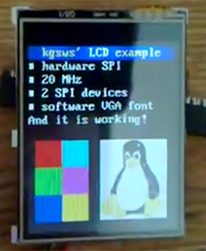
[kgsws] is using the native SPI pins on this module to control the clock and data lines for the tiny LCD, with a GPIO pin toggling the chip select. I2S audio is also implemented, decoded with an 8-bit DAC, the MCP4801.
It’s an extremely inexpensive solution for putting audio and video in a project, and since this board has Ethernet, WiFi, and a few more GPIO pins, it’s can do much more than whatever [kgsws] is planning next.


Are you using openwrt as the image on these? If so how did you flash it?
He is using openwrt, you can download his mods if you follow the article link. Most people flash these via a tftp server with boot (just go to https://openwrt.org, there are details on how it is done.
From his readme:
First you have to compile OpenWRT:
– https://github.com/JiapengLi/OpenWrt-HiLink-HLK-RM04
– http://wiki.openwrt.org/toh/hilink/hlk-rm04
– with kmod-spi-dev (Kernel modules -> SPI support)
– without kmod-leds-gpio (Kernel modules -> LED Modules) – otherwise you will have to change reset GPIO
TIP:
You can disable more modules that you won’t use.
What is your project? Do you need ipv6 support? Do you really need dnsmasq? Or USB support?
After sucessfull compilation, copy my included changes and compile again.
Note:
There is official support for HLK-RM04 in OpenWRT, however i am still using unofficial build.
You need to edit the dts file to truly get i2c enabled, beyond the menuconfig options. From what I remember, neither if those links discuss it. The jiapeng patch process is no longer necessary on current trunks.
I have a couple of these, flashed with the latest trunk (at the time) built on my x86 machine. You can follow the procedure from the openwrt website and it should work: 1. replace uboot 2. flash using tftp
http://wiki.openwrt.org/toh/hilink/hlk-rm04#step.by.step
There was an image that claimed to be a “flash via webpage firmware update” image I tried, but it just sat saying “uploading” for ages then the module dropped off the wifi and never came back. ( i waited hours ). A reboot brought it back up with normal factory image.
Do you need to do the firmware update over a wired connection? I have not hooked up the Ethernet cables yet, just using wifi.
yes, I’ve done everything through wired connection, soldered a rj45 jack with builtin ‘magnetics’ to the pins. An another computer running linux and the tftp daemon created a alias for the ethernet device on the IP range expected by the tftp request coming from the hlk board. I also have the rx/tx uart pins connected to a usb-ttl rs232 adapter, since it’s needed to direct uboot to make the tftp request.
If you build from the current trunk you do not need the patches from jipeng. However you still need to make the kernel config tweak for 16M ram. Wifi is disabled in lua by default, so you have to log in via ether or serial and enable it.
Nice. Not as cheap as the TL-WRT703n (also has wifi, ethernet, gpios, uart…), but kudos on ending up with a working setup – I started doing similar on the WRT, but lost interest after I’d proved hardware SPI working from a patched OpenWRT.
Maybe one day I’ll finish a project…
Couldnt be done with tplink
TL-WRT703n = AR9331 has I2S on paper, but nobody has documentation :( so no drivers for it
But it does have USB, and usb soundcards are cheap
It’s cheap. The ~25 price tag includes the dev board. The rm04 themselves are only ~16
Thank you, this is a nice share. will try this one. dont understand really about the 470 ohm resistor on lcd data line.
Noobi question its is possible to stream in the same way I2S from an ADC device?
Thx
Sorta. An I²S audio source (e.g. from an ADC) generates the clock, so whatever’s receiving the audio would have to act as a SPI slave. Additionally, I think there’s no requirement that I²S be a multiple of 8 bits per word (although most of them are), and many SPI hardware devices get confused if they’re not receiving octets. Finally, the word clock line has a different meaning than SPI’s normal chip select. None of these are unsurmountable.
They do make ordinary SPI ADCs, which is probably easier.
quick question. Could someone help me get the model of that tiny LCD? looks amazing.
Search for 2.2 inch spi lcd, it uses the ILI9225B IC Driver (he has his SPI library in the download on his blog post). The IC driver chip supports 240×320 and 177×220 and he is using the lower res one. PJ22002A is a common part number for that resolution, but there are lots of other part numbers in use, so the big thing is the resolution and that they are using the ILI9225B. There are also quite a few libraries out there for that driver chip, some bare bones to save flash/ram, others with GUI widget libraries…
These are available from lots of different sources, so depending on where you are, you might find ones local (same country). For ones that are PCB mounted with header pins and an SD card slot, there are vendors from China on Ebay selling them for about $6USD (+$2 for shipping) currently. Also you can find the non-mounted versions that you would need to add a ZIF connector to your PCB so you could use the flex connector (I’ve bought this for 1 buck each qtys of 5+ directly from Chinese vendors with a few bucks for shipping, they are flat thus slip right into a padded flat-pack. Skip the ZIF, and just solder jumper wires to the flex connector for a REAL cheap LCD solution, but the mounted ones with header pins easy for breadboarding.