NeoPixels, or WS2812 RGB LEDs, are the display device du jour for impressive and blinding lighting projects. Commonly known for very tight timing requirements, [Josh] discovered this is, in fact, usually unnecessary. The timing requirements for NeoPixels aren’t as bad as they seem, once you get to know them.
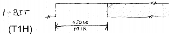
The official WS2812 timing specs give values that are fairly constraining for anyone writing a library to drive these RGB LED pixels, but simplifying the timing diagram by assuming a 50% duty cycle on the data lines and ignoring the longer maximum times results in a surprising conclusion: the only tight timing parameter for NeoPixel signaling is the maximum width of the 0-bit pulse.
Realizing this, [Josh] wrote a simple demo program to drive over 1000 NeoPixels – an 11 meter long strip – using 1K of RAM on an Arduino. The trick comes by simply delaying the bitbanging a set number of cycles. No obtuse assembly required.
There is only one problem with [Josh]’s method of driving a nearly unlimited amount of NeoPixels – building a display where every NeoPixel is an element in a larger image, such as in a video display, is impossible on systems with limited amounts of RAM. The code writes values to the NeoPixel strip algorithmically, so if you can’t build your animation with for loops, you’re out of luck. Still, Driving this many NeoPixels is a migraine trigger, and we have to give [Josh] credit for doing this with 1K of RAM.
Check out the video of [Josh]’s extreme NeoPixel strip below.


I was really waiting for someone to try this as I didn’t have time myself. Thanks @Josh.
So just upgrade to a larger platform. the Pi will easily do 100,000 of these and still have a ton of ram left over.
Cool story bro.
You completely missed the point man…
No waaaaay!, Just upgrade to an NVIDIA GPU, you can easily drive a 4K display with it
What RTOS do you recommend for the RPi?
The trick with these modules is that the first LED in line fixes up the timing before it dumps the signal on to the remaining chain. Providing you can get close enough to what it wants and don’t wait for 50mS or longer between pixels then you’re effectively unlimited over the number of pixels you can drive. If, on the other hand, you want to update the strip at 50 frames/second then you have an upper limit of about 600 LEDs in a line per channel, or about 10 metres of the common 60 LEDs/metre strip.
Wait, Neopixel and WS2812 are the same chip?
NeoPixel is what Adafruit call their WS2812 and WS2811 LEDs and strips, so yes, they’re the same.
It’s the Adafruit Kleenex. Or Xerox. Or something.
Sorry Brian, I am off course less expert then you..but what I am trying to do is make a color wipe with not constant speed but in increasing speed. What I have to change to have less time between two leds switch on? What is the parameter that I have to change?
Thank you
Andrea
I remembered it was a hell of a timing issue with a neopixel ring I once ordered, and just got that exactly right before [fail] and blew it up :]
But this.. this is awesome, good job!
Test the leds individually, accidentally bumped the PSU to 12V and “burned” my strip, turns out only 2 burned leds where affecting the whole strip
Thanks, I will try that, I didn’t throw it yet.
Nice writeup. I figured the timing wasn’t too strict when I wrote 8051 code to drive them, but didn’t realise it was quite this slack…
Interesting, everyone else says that the timing needs to be very accurate. Can you elaborate?
Hackaday keeps saying the timing needs to be very accurate. Myself and others have mentioned in the comments multiple times that it isn’t that strict.
Really? So it would be feasible to control them with a PIC microcontroller?
There’s absolutely no reason why you couldn’t! At absolute worst you’d reduce the number of LEDs you can drive to accommodate for lower-end PICs with less RAM (or you could just use a PIC with as much horsepower as the Arduino)
Or you can pack the bits and reduce colour resolution to get more LEDs driven, for example, your framebuffer can be 64 bytes and still drive 128 LEDs if you use four bits per pixel – this will only give you 16 possible colours (including ‘black’), but it’ll work
When you run a lightstrip in this way, RAM means nothing ! sure you need a few bytes for delays and loops, but you don’t need to store information for every single pixel. Even the smallest microcontroller could do this.
im not 100% confident you know about the WS2812 and how they’re driven …
Brian is right, very little RAM is needed when doing simple patterns as shown in the video. Just a bunch of for loops.
you need to store the value for each pixel before sending them unless you want to overclock your AVR or stick with painfully simple algorithms
Looking at the article, it seems there must be no more than 5us between each 3 bytes (RGB) sent, at 20MHz that’s 100 clock cycles to process the colour of the next pixel, plenty of time for a decent algo.
Exactly how complex do you think you’re going to get with a 1 dimensional array? We’re talking about a chaser circuit here. Obviously if he were to create a 2D array and wanted to display video, he would need more ram, but even with a 2D array you could create some pretty nifty color gradient effects with a few for loops and some math and you wouldn’t have to store more than a few bytes of data to do it.
“Exactly how complex do you think you’re going to get with a 1 dimensional array? We’re talking about a chaser circuit here. Obviously if he were to create a 2D array and wanted to display video, he would need more ram, but even with a 2D array you could create some pretty nifty color gradient effects with a few for loops and some math and you wouldn’t have to store more than a few bytes of data to do it.”
… kids nowadays…, they don’t know that there is no such thing as 2D arrays… SMH
“… kids nowadays…, they don’t know that there is no such thing as 2D arrays… SMH”
Woah there, Mr. Condescending Attitude.
From wikipedia: “An array is a systematic arrangement of objects, usually in rows and columns.”
The fact that some programming languages limit array data structures to only 1-dimension doesn’t mean other types of arrays don’t exist. And, even if you want to make the case that you were referring to array data structures in the arduino programming environment, it’s pretty clear that OP was referring to a 2D array of led pixels, not a data structure.
Dr. Z.
On the contrary, I found him extremely condescending when he said that “this is just a 1D array, we are talking about a chaser circuit here”. In my opinion he completely missed the point.
I wanted to point out that while YES, this IS a 1D array, NO, we are NOT talking about a chaser circuit here. I wanted to emphasize that you don’t need (and as a matter of fact, don’t want) a 2D array to do image/video operations.
I was not referring to any specific language, I was referring to decent (<- that's being condescending) programming practices.
i have always just used ARMs for neopixels
What I’ve done is tweaked a version of my ws2811 code to work with 8bit RGB (RRRGGGBB) spitting out 0s except for the few bits of actual RGB value. I lose much of the colour gamut sure, but nobody cares and I can work with/generate fancy bitmaps in the memory constraint of a plain AVR
“The official WS2812 timing specs give values that are fairly constraining for anyone writing a library to drive these RGB LED pixels”
No, they do not. I read this all the time, together with overcomplexe generated code to solve the “problem”, but you can do it rather easily.
Here is some code to send green byte on a 9.8MHz Attiny13. This took like 15 minutes to write and test :
ldi r16, 8 ; bit counter
WS2812_green_bit:
sbi PORTB, PORTB4 ; L6-L8-H0 L3-L5-H0
lsl r11 ; H0-H1 H0-H1
sbrs SREG, C ; H1-H2 H1-H3
sbi PORTB, PORTB4 ; H2-H4-L0 —–
nop ; L0-L1 H3-H4
sbi PORTB, PORTB4 ; L1-L3 H4-H6-L0
dec r16 ; L3-L4 L0-L1
brne WS2812_green_bit ; L4-L6 L1-L3
Just copy/paste 3 times for RGB. This code is fully compliant with the timing given by the datasheet. There are easy ways to get 1 or 2 free cycles so the code run at 8MHz (reverse the test, and/or replace write a whole byte instead of just a bit on PORTB.
The datasheet says that you need to wait at least 50µs to reset the chain of bytes. It needs less than that to reset, but you still have plenty of time after you send the RGB value to load (or interpolate) next value and loop.
I tested the code on an Attiny13A runnning at 9.6MHz on internal timing signal, it can run 4-5 WS2812 without the mandatory capacitors. It can drive a leds strips.
Fabien.
(“L6-L8-H0″ means ” have been Low for 6 Cycle when instruction starts, Have been Low for 8 cycles when instruction ends, turns High at the end of instruction. Left columns is for sending a 0, right columns for when you send a 1)
DDR-2 SDRAM manufacturer DDR-1 SDRAM specifications. Like DDR-1 SDRAM, it also transfers data on both rising and falling edges of bus clock signal, but also, it runs the internal clock at half the speed of the data bus. Thus, DDR2 memory operates almost at twice the external data bus clock rate as DDR may provide twice the bandwidth with the same latency.
Hey, could this be possible with WS2811 and Artnet?
The only project i found for that could handle 340LEDs with an Arduino Mega and only 170 with an Uno.
There is a new product to control multiple NeoPixel strips/channels, up to 16 channels!
Check it out:
http://www.ebay.com/itm/WS2812-NeoLeds-splitter-extender-mux-multiplexer-for-arduino-/132139993810
Would it be possible to use this for led strips on multiple digital outputs with multiple led strips
Hi, réally good job ????, have you test this technic ethernet on Arduino? I think its impossible because There isnt enough RAM, Can you confirm?
Thanks ????????