[Ken Shirriff] had to get down into a bit of semiconductor physics to give us an explanation of the TL431, which he calls “the most common chip you’ve never heard of”. [Ken] may well be right about the TL431. Even Texas Instruments can’t nail down a single name for it. Their page for the part calls it a “Adjustable Precision Shunt Regulator”, yet the datasheet is titled “Precision Programmable Reference”. You’d think they’d have figured this out by now, considering the TL431 was launched in 1978.
TL431’s can most often be found hiding in switching power supplies. The Apple II switcher had one, and many current ATX supplies have 3. Uninformed parts scroungers may miss them, as they often hide in TO-92 or SOT-23 packages. The TL431 is no transistor though. The TL431’s operation is actually pretty simple. When the voltage at the reference pin is above 2.5V, the output transistor conducts. When the reference voltage falls below 2.5V, the device stops conducting. In a power supply, this operation would help the control electronics maintain a stable output voltage.
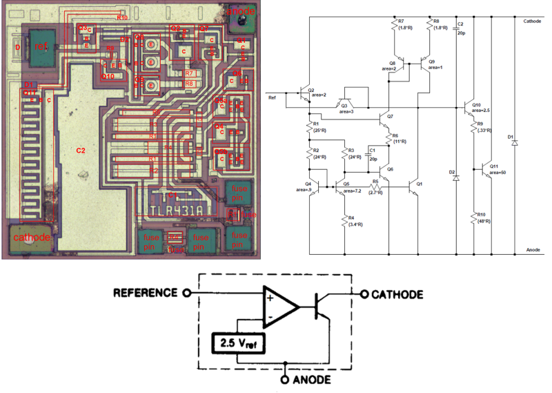
The real subject of [Ken’s] article is the layout of the TL431 on its silicon die. Rather than bust out the fuming nitric acid himself, [Ken] uses some of [Zeptobars’] decapped chip images. Inside the TL431, [Ken] discovers that transistors aren’t made up of the three layer NPN or PNP sandwich we’ve come to know and love. In fact, the base isn’t even in the middle. Transistors, including the BJT’s used in the TL431, can be assembled in a nearly infinite number of ways.
[Ken] moves on to the resistors and capacitors of the TL431. The capacitors are formed two different ways, one as a reverse biased diode, and the other as a more traditional plate style capacitor. The resistors include fuses which can be blown to slightly increase the resistance values.
The takeaway from all this is that once you get down to the silicon level, it’s a whole new ball game. Chip layout may look a bit like PCB layout, but the rules are completely different. [Ken] mentions that in a future blog he’ll go into further detail on the operation of the TL431’s bandgap voltage reference. We’ll be watching for that one, [Ken]!


I had one providing an I/O voltage on the last board I did…
It’s a shunt regulator, so it’s only useful for known loads or cases where the current draw is minimal and unimportant, but it intrinsically provides startup tracking, which can be hard to find in a regulator.
They can be used as an audio amp too. http://www.techlib.com/electronics/audioamps.html#TL431
It is one of those ubiquitous oddballs I’ve come to love, and I dare say have used more than the venerable 555 and its descendants. Nice write-up, and I really dig seeing the bare-die details!
This article also reminds me of another little-known device: the LM134 family. It’s a 3-terminal adjustable current source, for which I’m finding a lot of use lately in sensor-interface applications. Another one of those “it exists but no-one knows it” devices, but it’s proven extremely handy in reference-current and temperature-monitoring applications.
The TI and ON data sheets each contain dozens of possible uses for the LM134 too, something I would love to see in other parts’ data sheets. IIRC, National Semiconductor’s were *awesome* in this respect, in years past.
I have seen it in a lot of places. e.g. old (ISA) video card as a reference source for video DAC.
Also one neat application is that you can use it as a (slow) voltage comparator. It gets rid of the comparator input offset (easily 5 – 10mV!) introduced by a separate comparator.
The only complain I have about this particular part is the 1mA minimum loading and the what I called “Puffer fish” chef’s diagram (as from The Simpson) on the stability graphs that show the capacitance load that it is stable under. It should not be used without reading and *understanding* the datasheet.
It is/was also very popular as a secondary side feedback circuit for the regulated AC/DC switcher bricks. They typically use a voltage divider network for the voltage set point (along with a RC frequency compensation network) and the “error” is sent as a current via an optocoupler back to the primary side of the flyback circuit.
These days, some bricks are unregulated (i.e. no feedback) just to save that $0.35.