Two-Cent Temperature Sensors

When they need to add temperature control to a project, many hackers reach for a K-type thermocouple for their high-temperature needs, or an integrated temperature-sensing IC when it doesn’t get that hot. The thermocouple relies on very small currents and extremely high gain, and you pretty much need a dedicated IC to read it, which can be expensive. The ICs aren’t as expensive, but they’re basically limited to boiling water. What do you do if you want to control a reflow oven?

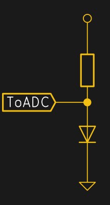
There’s a cheaper way that spans a range between Antarctic winter and molten solder, and you’ve probably already got the parts on your shelf. Even if you don’t, it’s only going to run you an extra two cents, assuming that you’ve already got a microcontroller with an ADC in your project. The BOM: a plain-vanilla diode and a resistor.

I’ve been using diodes as temperature sensors in three projects over the last year: one is a coffee roaster that brings the beans up to 220 °C in hot air, another is a reflow hotplate that tops out around 210 °C, and the third is a toner-transfer iron that holds a very stable 130 °C. In all of these cases, I don’t really care about the actual numerical value of the temperature — all that matters is reproducibility — so I never bothered to calibrate anything. I thought I’d do it right for Hackaday, and try to push the humble diode to its limits for science.

What resulted was a PCB fire, test circuits desoldering themselves above 190 °C, temperature probes coming loose, and finally a broken ramekin and 200 °C peanut oil all over my desk. Fun times! On the other hand, I managed to get out enough data to calibrate some diodes, and the results are fantastic. The circuits under test included both best practices and the easiest thing that could possibly work, and the results are pretty close. This is definitely a technique that you want to have under your belt for most temperature ranges. The devil is in the details, of course, so read on!

Continue reading “Two-Cent Temperature Sensors”

[Ken Shirriff] Explains The TL431

[Ken Shirriff] had to get down into a bit of semiconductor physics to give us an explanation of the TL431, which he calls “the most common chip you’ve never heard of”. [Ken] may well be right about the TL431. Even Texas Instruments can’t nail down a single name for it. Their page for the part calls it a “Adjustable Precision Shunt Regulator”, yet the datasheet is titled “Precision Programmable Reference”. You’d think they’d have figured this out by now, considering the TL431 was launched in 1978.

TL431’s can most often be found hiding in switching power supplies. The Apple II switcher had one, and many current ATX supplies have 3. Uninformed parts scroungers may miss them, as they often hide in TO-92 or SOT-23 packages. The TL431 is no transistor though. The TL431’s operation is actually pretty simple. When the voltage at the reference pin is above 2.5V, the output transistor conducts. When the reference voltage falls below 2.5V, the device stops conducting. In a power supply, this operation would help the control electronics maintain a stable output voltage.

The real subject of [Ken’s] article is the layout of the TL431 on its silicon die.  Rather than bust out the fuming nitric acid himself, [Ken] uses some of [Zeptobars’] decapped chip images. Inside the TL431, [Ken] discovers that transistors aren’t made up of the three layer NPN or PNP sandwich we’ve come to know and love. In fact, the base isn’t even in the middle. Transistors, including the BJT’s used in the TL431, can be assembled in a nearly infinite number of ways.

[Ken] moves on to the resistors and capacitors of the TL431. The capacitors are formed two different ways, one as a reverse biased diode, and the other as a more traditional plate style capacitor. The resistors include fuses which can be blown to slightly increase the resistance values.

The takeaway from all this is that once you get down to the silicon level, it’s a whole new ball game. Chip layout may look a bit like PCB layout, but the rules are completely different. [Ken] mentions that in a future blog he’ll go into further detail on the operation of the TL431’s bandgap voltage reference. We’ll be watching for that one, [Ken]!